Important – Huffy DC910 User Manual
Page 14
14
P/N 211455F
08/03
24
19
22
21
23
20
12.
24
13.
18
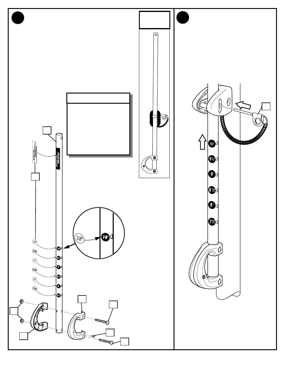
Insert handle assembly
through pole mount
assembly as shown. Lock
pole assembly in place at
the 10’ (3.05 m) mark with
pin (18).
Apply logo and height indicator
labels (19) to adjustment rod (20) as
shown. Attach handle parts (21, 22)
to adjustment rod with screw (23),
carriage bolt (24), and flange nut (9)
as shown.
NOTE: Holes in adjustment rod allow
for either rear access or side access.
Indicator labels should
be applied as close to
holes as possible (as
shown in illustration)
to prevent labels from
being damaged during
height adjustment.
IMPORTANT!:
9
SIDE
ACCESS
See also other documents in the category Huffy Sports and recreation:
- GOGEAR SA2820 (4 pages)
- N1-506 (33 pages)
- 1051 (13 pages)
- DC177 (28 pages)
- M581704 (27 pages)
- MQX-2310 (18 pages)
- 1310 (24 pages)
- RC5200 (16 pages)
- 104/03P/N211956B (13 pages)
- M661134 (62 pages)
- SKM 1030 (35 pages)
- DOLPHIN 7900 (55 pages)
- M781921 (5 pages)
- 32PFL3403D (6 pages)
- M8000 (18 pages)
- D 50053 (17 pages)
- M5800151 (30 pages)
- Fitness Equipment (33 pages)
- ATVUSB05 (31 pages)
- SKYIPCAM650W AICAP650W (14 pages)
- SR 3254 (1 page)
- M611814 (30 pages)
- UXT2030AA (51 pages)
- M881104 (40 pages)
- 8000 (14 pages)
- M580001 (14 pages)
- 110-816R019 (15 pages)
- MCM108DB (17 pages)
- PRESTIGE V 450 (30 pages)
- AC4054 (18 pages)
- M611804 (29 pages)
- SA3246 (10 pages)
- 214994C (24 pages)
- AR325W (33 pages)
- 7000MXP (25 pages)
- M7800041 (14 pages)
- DEP 800 (4 pages)
- SKM 3072-U (11 pages)
- SKM 5200 (14 pages)
- 11S0057 (25 pages)
- MX4006 (38 pages)
- 214946C (25 pages)
- WIRELESS PCI ADAPTER AWLH4030 (29 pages)
- FR320UKT (14 pages)
- OFFICE NAS ANAS350 (22 pages)