Heat & Glo Fireplace 8000TRD User Manual
Page 26
26
Step 4. Positioning, Leveling, and
Securing the Fireplace
• Place the fireplace into position.
• Level the fireplace from side to side and front to back.
• Shim the fireplace with non-combustible material, such
as sheet metal, as necessary.
• Secure the fireplace to the framing by nailing or screwing.
!
!
The diagram below shows how to properly position, level,
and secure the fireplace.
Figure 34. Proper Positioning,
Leveling and Securing of a Fireplace
Step 5. The Gas Control Systems
WARNING: THIS UNIT IS NOT FOR USE WITH
SOLID FUEL.
Two types of gas control systems are used with these models:
Standing Pilot Ignition and Intermittent Pilot Ignition (IPI).
Standing Pilot Ignition System
This system includes millivolt control valve, standing pilot,
thermopile/thermocouple flame sensor, and piezo ignitor.
WARNING: 110-120 VAC MUST NEVER BE
CONNECTED TO A CONTROL VALVE IN A
MILLIVOLT SYSTEM.
Intermittent Pilot Ignition (IPI) System
This system includes a 3V control valve, electronic module
and intermittent pilot.
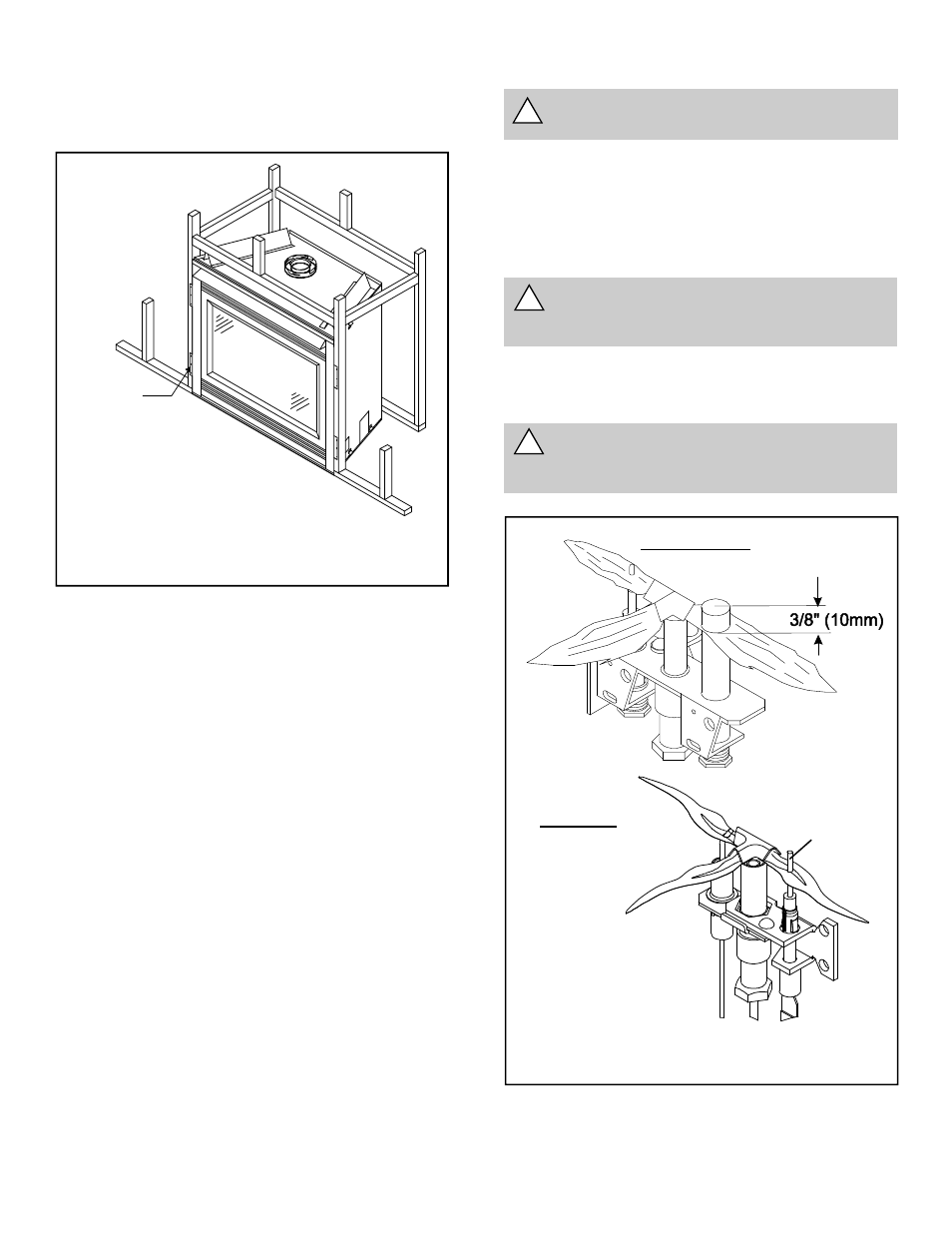
Figure 35. Gas Control Systems
NOTE:
Flames too close to the ceramic insu-
lators can cause nuisance lockouts
and electrode failure.
IPI IGNITION
STANDING PILOT
NAILING TABS
(BOTH SIDES)
!
WARNING: CONTINUOUS 110-120 VAC SER-
VICE MUST BE WIRED DIRECTLY TO THE FIRE-
PLACE JUNCTION BOX.
u
FLAME SENSOR
ROD