D. frame the fireplace, C. sidewalls/surrounds – Hearth and Home Technologies Heatilator FL92 User Manual
Page 20
20
11.92 in.
[303 mm]
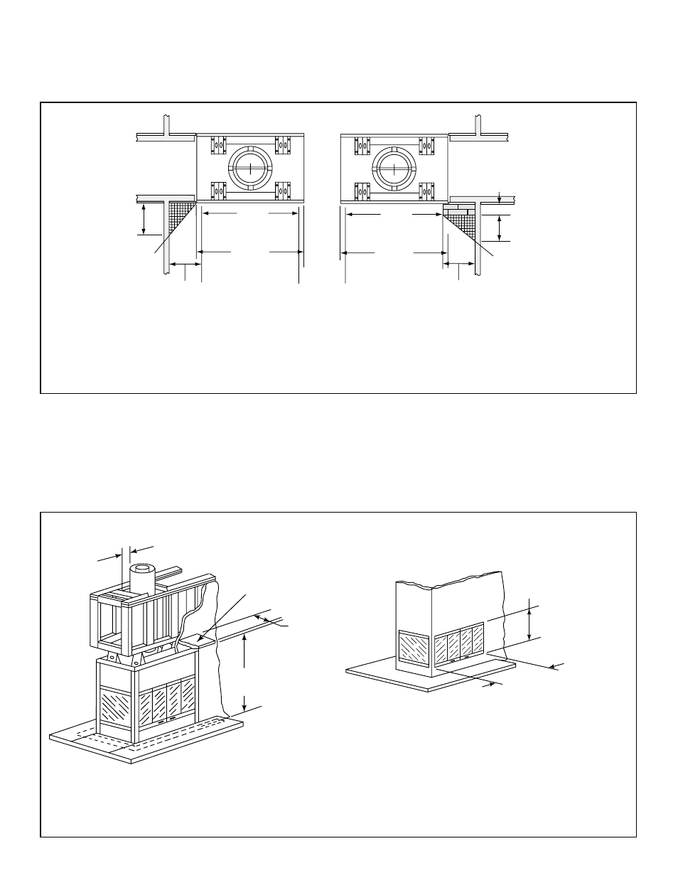
FLUSH
FRONT
40 in.
[1016 mm]
36 in.
[914 mm]
(fireplace opening)
12 in.
[305 mm]
50° angle
9 3/4 in.
[248 mm]
4 in.
[102 mm]
BRICK
FRONT
40 in.
[1016 mm]
36 in.
[914 mm]
(fireplace opening
12 in.
[305 mm]
39° angle
D. Frame the Fireplace
Figure 6.4 shows typical framing using combustible materials (2x4 lumber shown).
• Observe all required air space clearances to combustible materials as shown in Figure 6.1 & 6.2.
• Framing across the top of fi replace must be above top standoffs.
36 in. min.
(914 mm)
22-1/2 in.
(572 mm)
47-1/8 in. (1197 mm) header height. Use only
noncombustible material below the standoffs.
2 in. (51 mm) Minimum Air Space
Clearance to Enclosure
12 in.
(305 mm)
maximum
42-1/2 in.
(1080 mm)
Mantel
Figure 6.4 Framing the Fireplace
C. Sidewalls/Surrounds
• Adjacent combustible sidewalls must be located a minimum of 12 in. (305 mm) from the fi replace opening.
• Combustible and noncombustible mantel legs, surrounds and stub walls may be constructed within the gridded area,
Figure 6.3.
Figure 6.3 Mantel Leg or Wall Projections
Heatilator • Multi-Sided Woodburning Fireplace • 34955 • Rev V • 11/08