Eg o l c – Hunter Fan 43168 User Manual
Page 21
40
41
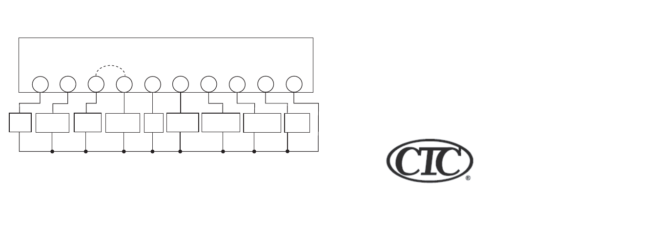
WIRING DIAGRAM
R
B
W2
E
G
O
L
C
Y2
Y1
THERMOSTAT WALLPLATE TERMINALS
24V
Supply
Reversing
Valve Heat
Auxiliary
Heat
Emergency
Heat
Fan
Relay
Reversing
Valve Cool
Compressor
Stage 2
Compressor
Stage 1
System
Monitor
Common
NOTE: Common connection is REQUIRED.
* On systems without and E wire,
add jumper between W2 and E.
Optional jumper *
Climate Technology Corp.
2500 FRISCO AVENUE
MEMPHIS, TN 38114
© 2008, Climate Technoogy Corp.
A Hunter Fan Company
Form No. 44014-01, r010408
www.climatetechnologyproducts.com
See also other documents in the category Hunter Fan Control panel:
- 44272 (2 pages)
- 47110A (2 pages)
- 47350A (23 pages)
- 44428 (22 pages)
- 40170 (33 pages)
- 47250A (7 pages)
- 44132 (2 pages)
- 42122 (25 pages)
- 44033-01 44277 (37 pages)
- 43154 (7 pages)
- SET & SAVE 44155C (52 pages)
- 44550 (38 pages)
- 40135 (30 pages)
- 44377W (64 pages)
- 44905 (54 pages)
- 42999 44050S (23 pages)
- 42710-01 (58 pages)
- 44050 (24 pages)
- 44008-01 (100 pages)
- 144860 (76 pages)
- 43255 (7 pages)
- 47550 (38 pages)
- 44660 (2 pages)
- 44377 (45 pages)
- 43057 (13 pages)
- 44459 (40 pages)
- PH20-30A (26 pages)
- 44665 (2 pages)
- 43157 (2 pages)
- 42711-01 (55 pages)
- 47300A (44 pages)
- 44760 (28 pages)
- 44110 (52 pages)
- 44127 (37 pages)
- 44260 (104 pages)
- 43665 (49 pages)
- 43355 (43 pages)
- 47200A (7 pages)
- 43153 (2 pages)
- 40120 (28 pages)