Rear-panel connections – Harman-Kardon AVR 630 User Manual
Page 8
8
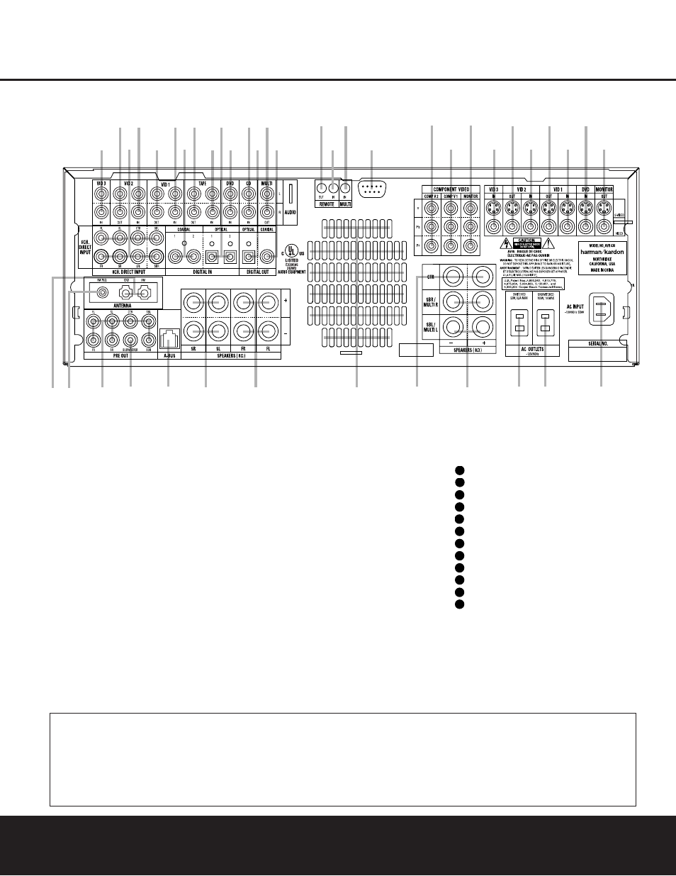
REAR-PANEL CONNECTIONS
REAR-PANEL CONNECTIONS
¡ AM Antenna
™ FM Antenna
£ Preamp Outputs
¢ Subwoofer Output
∞ A-BUS Connector
§ Surround Speaker Outputs
¶ Front Speaker Outputs
• Fan Vents
ª Center Speaker Outputs
‚ Surround Back/Multiroom Speaker Outputs
⁄ Switched AC Accessory Outlet
¤ Unswitched AC Accessory Outlet
‹ AC Power Cord Jack
› Video Monitor Outputs
fi DVD Video Inputs
fl Video 1 Video Inputs
‡ Video 1 Video Outputs
° Video 2 Video Inputs
· Video 2 Video Outputs
a Video 3 Video Inputs
b Component Video Monitor Outputs
c Component Video 1 Inputs
d Component Video 2 Inputs
e RS-232 Port
f Multiroom IR Input
g Remote IR Input
h Remote IR Output
i Coaxial Digital Audio Output
j Multiroom Audio Outputs
k Optical Digital Audio Output
CD Audio Inputs
DVD Audio Inputs
Optical Digital Audio Inputs
Tape Inputs
Tape Outputs
Coaxial Digital Audio Inputs
Video 1 Audio Inputs
Video 1 Audio Outputs
Video 2 Audio Inputs
8-Channel Direct Inputs
Video 2 Audio Outputs
Video 3 Audio Inputs
42
41
40
39
38
37
36
35
34
33
32
31
NOTE: To assist in making the correct connections for
multichannel input, output and speaker connections,
all connection jacks and terminals are color-coded
in conformance with the CEA standards as follows:
Front Left:
White
Front Right:
Red
Center:
Green
Surround Left:
Blue
Surround Right:
Gray
Surround Back Left:
Brown
Surround Back Right:
Tan
Subwoofer:
Purple
Digital Audio:
Orange
Composite Video:
Yellow
Component Video “Y”: Green
Component Video “Pr”: Red
Component Video “Pb”: Blue
REAR-PANEL CONNECTIONS
8
REAR-PANEL CONNECTIONS
NOTE: To make it easier to follow the instructions that refer to this illustration, a larger copy may be downloaded from the Product Support section for this product at
www.harmankardon.com.
4
5
6
7
8
9
A B
C
D
E
F
G
J
H
I
K
L
U
T
S
R
Q
P
O
N
M
d
c
f
e
Z
Y
X
W
V
a
b
0 1
3
2