Henny Penny HUMIDIFIED COUNTER WARMER HCW-8 User Manual
Page 11
Model HCS-2/HCW-3/HCW-5/HCW-8
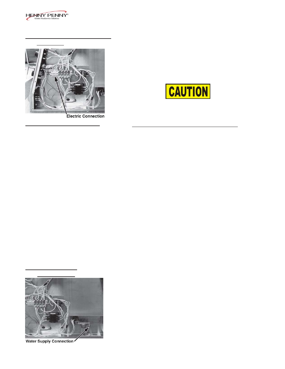
2-6. ELECTRICAL CONNECTION
The electrical power can be connected from the bottom or from the
(Continued)
operator’s side. There is a 1-3/32 inch diameter hole for either
connection. Again, we recommend the bottom connection as this
will give a cleaner appearance to the unit. Please observe the
electrical connection information on the data plate located on the
side panel of the control end.
Voltage potential of L1 and L2 to ground cannot exceed
125 volts, or damage to the unit could result.
2-7. ELECTRIC DATA TABLE
Model
Volts
Phase Watts
Amps
HCW-2
120/230
1
760
4.7
HCW-2
120/208
1
760
4.9
HCS-2
230
1
2852
12.4
HCW-3
120/230
3
3400
10.7
HCW-3
120/230
1
3400
16.3
HCW-3
120/208
3
3400
11.5
HCW-3
120/208
1
3400
17.6
HCW-3
400
3
3400
5.0
HCW-5
120/230
3
4160
12.2
HCW-5
120/230
1
4160
18.0
HCW-5
120/208
3
4160
13.1
HCW-5
120/208
1
4160
19.5
HCW-5
400
3
4160
6.0
HCW-8
120/208
3
8080
26.0
HCW-8
120/208
1
8080
40.0
HCW-8
120/230
3
8080
24.0
HCW-8
120/230
1
8080
35.1
HCW-8
400
3
8080
11.7
HCS-5
120/208
3
8080
22.6
HCS-5
120/208
1
8080
40.0
HCS-5
120/230
3
8080
19.8
HCS-5
120/230
1
8080
35.1
HCS-5
400
3
6680
9.7
2-8. WATER SUPPLY
The automatic water system has a 1/4 inch compression fitting for
CONNECTION
copper tubing. Hot water would be preferred. We recommend
using the automatic water system as this will allow the unit to
maintain a more even water temperature and help ensure that the
unit never runs dry of water.
A straight-through bulkhead fitting is furnished with the unit for
1/4 inch copper tubing to protect the water line where it passes
through the sheet metal.
Reinstall the end panel.
1006
2-5