Controls, Control locations – Husqvarna 966582201 User Manual
Page 17
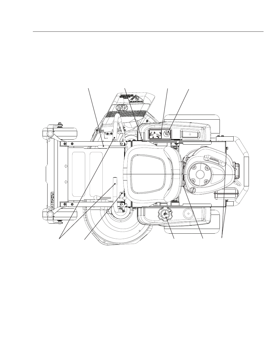
ContRoLs
17
This operator’s manual describes the Husqvarna Zero
Turn Rider. The rider is fitted with a Briggs & Stratton
19 HP* four-stroke overhead valve engine.
Transmission from the engine is made via belt-driven
hydraulic pumps. Using the left and right steering
controls, the flow is regulated and thereby the
direction and speed.
Cutting height handle
1.
Park brake
2.
Throttle / choke control
3.
Ignition switch
4.
Motion control levers
5.
Blade control lever
6.
Fuel tank cap
7.
Fuel shut off valve
8.
Bypass linkage
9.
Control Locations
1
2
3
4
5
6
8
9
7
8058-070-1
*The power rating of the engines indicated is the average
net power output (at specified rpm) of a typical production
engine for the engine model measured to SAE standard
J1349/ISO1585. Mass production engines may differ from
this value. Actual power output for the engine installed
in the final machine will depend on the operating speed,
environmental conditions and other variables.
- 128LD (71 pages)
- 125B (47 pages)
- HEDGE TRIMMER ATTACHMENT (32 pages)
- 2754 GLS (49 pages)
- 532424761R1 (48 pages)
- 650CRT (28 pages)
- 1200-18 (68 pages)
- 324LD (32 pages)
- 324LD (28 pages)
- Hedge Trimmer 123HD65X (24 pages)
- 96045000410 (45 pages)
- 325L (36 pages)
- 966582101 (56 pages)
- 7021CP (18 pages)
- 11 (56 pages)
- 325HDA65X-Series (24 pages)
- 325HE4 x-series (24 pages)
- 323HE3 (24 pages)
- 326HD60 (24 pages)
- 5521RS (22 pages)
- Viking CA 150 (12 pages)
- 20 ProFlex (48 pages)
- 70 LP (8 pages)
- 326ES (32 pages)
- 250R (48 pages)
- 232L (32 pages)
- 227L/LD (32 pages)
- 965921501 (76 pages)
- 250 R (52 pages)
- 7021F (21 pages)
- 965969401 (8 pages)
- 210 C (50 pages)
- 210 C (48 pages)
- 966614401 (72 pages)
- 6022SH (18 pages)
- DRT 900 DRT 900 (29 pages)
- 142 RB (29 pages)
- 380 (9 pages)
- 96143005700 (18 pages)
- T 50RS (21 pages)
- 1200 (35 pages)
- 1200 (40 pages)
- H342SG (10 pages)
- 326R (36 pages)
- 125LDx (23 pages)