Husqvarna 917.377231 User Manual
Page 8
8
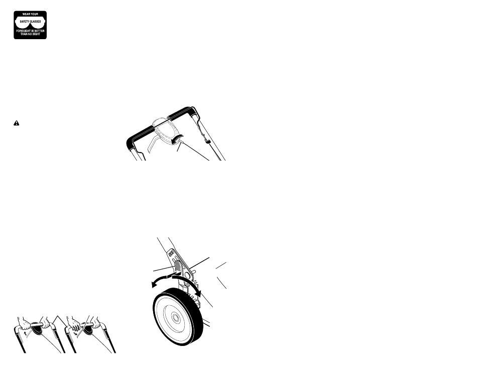
DRIVE CONTROL ADJUSTMENT
Over time, the drive control system may
become “loose”, resulting in decreased
speed. There is a turnbuckle on the drive
control housing to increase tension on the
drive cable. Pro ceed as follows:
1. Turn unit off and disconnect spark plug
wire from spark plug.
2. Rotate turnbuckle on drive control to
increase drive speed.
3. Operate mower to test drive speed.
Readjust as required.
4. If condition fails to improve after the
above steps (forward speed remains
the same), your drive belt is worn and
should be re placed.
The operation of any
lawn mower can result
in foreign objects thrown
into the eyes, which can
result in severe eye dam-
age. Always wear safety glasses or eye
shields while operating your lawn mower
or performing any ad just ments or repairs.
We recommend a standard safety glasses
or wide vision safety mask worn over
spectacles.
HOW TO USE YOUR LAWN MOWER
ENGINE SPEED
Engine speed was set at the factory for
optimum performance. It is not adjustable.
ENGINE ZONE CONTROL
CAUTION: Federal regulations re quire
an engine control to be installed on this
lawn mower in order to minimize the
risk of blade contact injury. Do not un der
any circumstances attempt to de feat the
func tion of the operator con trol. The blade
turns when the engine is running.
• Your lawn mower is equipped with an
operator pres ence control bar which
requires the operator to be positioned
behind the lawn mower handle to start
and operate the lawn mower.
DRIVE CONTROL
• Self-propelling is controlled by hold-
ing the operator presence control bar
down to the handle and pulling the drive
control lever rearward to the handle.
The farther toward the handle the lever
is pulled, the faster the unit will travel.
• Forward motion will stop when either
the operator presence control bar or
drive control lever are released. To stop
forward motion without stop ping engine,
re lease the drive control lever only. Hold
op er a tor presence control bar down
against handle to con tin ue mowing
without self-propelling.
NOTE: If after releasing the drive control
the mower will not roll backwards, push
the mower forward slightly to disengage
drive wheels.
LEVER
BACKWARD
TO LOWER
MOWER
LEVER
FORWARD
TO RAISE
MOWER
Height
adjuster lever
Adjustment
turnbuckle
TO
ENGAGE
DRIVE
CONTROL
Drive control
lever
DRIVE
CONTROL
DISENGAGED
Operator presence control bar
TO ADJUST CUTTING HEIGHT
All four wheels are adjusted by a single
lever.
• Pull adjuster lever toward wheel. To
raise mower, move lever forward to
desired position. To lower mow er, move
the lever toward the rear.
41
HUSQV
ARNA
ROT
AR
Y
LA
WN MOWER - - MODEL
NUMBER
917.377231
(PRODUCT NUMBER 7021RD)
NOTE:
All component dimensions given in U.S. inches. 1 inch = 25.4 mm.
IMPORT
ANT
: Use only Original Equipment Manufacturer (O.E.M.) replacement parts. Failure to do so could be hazardous, damage your lawn mo
wer and void your warranty
.
KEY
P
ART
NO. NO.
DESCRIPTION
KEY
P
ART
NO. NO.
DESCRIPTION
1
425581
Drive Control
Assembly
2
406260X460
Cover
, T
o
p
3
406262
Pulley
4
425583
Lever
, Drive Control
5
406261X460
Cover
, Bottom
6
181698
Screw
7
400235X479
Mounting Bracket
9
406258
Cable, Drive
1
1
406558
Spring, Return
13
419213
Gear Case
Assembly
14
193443
Pulley
, Drive
15
88348
W
a
sher
, Flat
16
407147
Rod, Connecting
17
409616
Spring, Extension
18
418835X004
Spring, Selector
19
189808X428
Knob, Selector Spring
20
12000022
E-Ring 7/8
21
404838
Bearing, Support
22
191039
Bearing, Ball
23
161
1
1
8X004
Retainer
, Drive
Assembly
24
17060410
Screw
, T
apping, Hex Head 1/4-20 x 3/4
25
199775X418
Cover Drive
26
750634
Screw
, Threaded, Rolled #10-25 x .50
28
12000058
E-Ring 7/16
29
189403
Cover
, Dust, Wheel
31
404845
Pawl
32
405746X460
Wheel & Tire
Assembly
, Rear 8 x 1-3/4
33
409148
Nut, Flangelock 3/8-16
34
851226
W
a
sher
35
403102X004
Shaft Assembly
,
Rear
36
407175X004
Shaft Assembly
,
Front
37
161463
Retainer
, Front Shaft
38
163409
Screw #12 x 5/8
39
407059
Bolt, Shoulder
, Semi-Gimlett Point
40
401273X460
Wheel & Tire
Assembly
, Front 8 x 1-3/4
41
404835
Pinion
42
197480
O-Ring
44
406580
V
-Belt
47
67725
W
a
sher
, Flat
49
163409
Screw
, Hi-Lo Thread
50
404832X004
Belt Keeper