Dh-222 installation instructions – Hafler DH-200 User Manual
Page 21
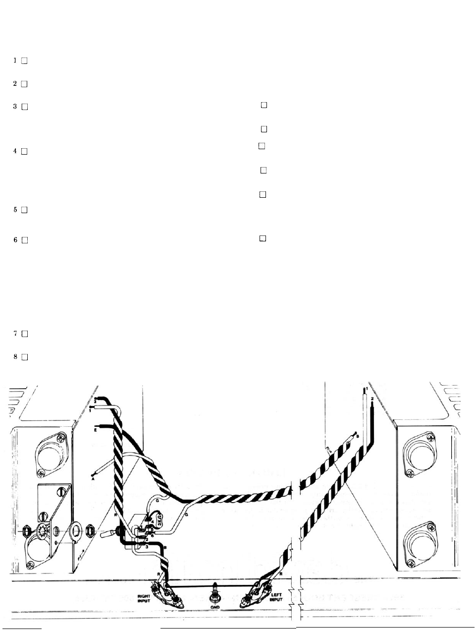
DH-222 INSTALLATION INSTRUCTIONS
Disconnect AC power from the amplifier, and remove all con-
necting cables. Wait 5 minutes to allow capacitors to discharge
before proceeding with disassembly.
Remove all 8 screws between the fins of each amplifier module
so that the cover may be removed, and the modules tilted out-
wards for easier access.
Unsolder the pair of twisted wires connected to holes 1 and 2 at
the top of the right channel PC-19 circuit board. The right
channel is the one nearest the power switch. This pair must
also be unsoldered from the right input socket on the back
panel, because it will be more convenient to use lighter gauge
wiring.
Prepare a 6%” red wire, and a 6 1/2" black wire. Start with the
black wire 1/2"”longer than the red wire, and twist them together
uniformly throughout their length. At the end where the black
wire projects, connect it to the short lug of the right input sock-
et. (S-2). Be sure the existing wire to the adjacent ground lug is
properly connected. Connect the corresponding end of the red
wire to the long lug of the input socket. (S). Place this pair off to
the right edge.
Prepare a 5%” red wire, and a 5%” black wire. With the ends
even, twist these together and connect ,the red wire to hole #l
at the top of the right channel PC-19 circuit board.
(S)
Connect
the black wire to hole #2. (S).
Prepare a 20”green wire. Cut a 20” black wire, but remove the
insulation from only one end. Starting with the bare end of the
black wire 1/2”longer than the green wire, twist these together.
At the far end, where the black insulation has not been re-
moved, the black wire will not be connected, but instead will be
secured by wrapping it in a tight circle around the green wire a
short distance from the bare green end. It is very important
that no bare wire be visible from the black insulation. The
single green wire is to be connected near the center of the lefi
circuit board to the hole designated “B”, located just below the
bias adjustment potentiometer. t
S).
It must be securely sol-
dered, but be careful that you do not damage adjacent compo-
nents.
Making sure that no wires are pinched between the module
and the chassis in the process, reinstall the left module to the
chassis with 4 sheet metal screws.
Select the switch and its 2 nuts, lockwasher and indexing flat
washer, and the switch mounting bracket. Install one nut all
the way onto the switch collar, and follow it with the indexing
washer with its lugprojecting towards the handle lever. Mount
the switch on the bracket so that the lever points in the direc-
tion of the bracket flange, and the indexing lug engages the
locating hole in the bracket. Secure it with the lockwasher and
the second nut.
9
Select the two machine screws and nuts, and install the switch
bracket between the two transistors at the rear of the right
module, so that the switch lever points towards the fins.
10
Select the 3000 ohm resistor and trim its leads to 1/2" Connect it
between switch lugs #4 and #5. Solder only lug #5.
11 Select the red and black pair from the right input socket and
12
13
I4
I5
16
connect the black wire to switch lug #3. Do not solder this con-
nection yet. Connect the red wire to switch lug #1. (S).
Select the red and black pair from the right channel circuit
board holes 1 and 2. Connect the black wire to switch lug #3.
(S-2). Connect the red wire to lug #2. (S).
Select the green and black pair and separate the wires for
about 1%“. Connect the green wire to right circuit board hole
“A”. (S). Connect the black wire to hole “E”. (S). Hole “A” is
located in line with the switch about 1 1/2” from the rear edge of
the board. “E” is located
1/2”
below hole 2, near the top of the
board.
Place the green and black pair towards the rear of the module,
and down past the midline of the switch. Where it passes lug
#5, approximately
the end of the wires, cut only the
green wire. Strip each end 1/4" Connect the short green section
to switch lug #4. (S-2): Connect the longer green wire from the
left board to switch lug #6. (S).
Be careful no wires are pinched as you reinstall the right mod-
ule to the chassis with 4 screws. Place the long green and black
pair under the rear lip of the chassis. The pairs to the top
eyelets on each board, and to the connections in the center of
the board should be kept at least off the board, where they
are clear of the components. Make sure the unconnected black
wire end near the left circuit board cannot touch any compo-
nents.
The switch lever should be placed in the upper position for
monophonic operation. In the lower switch position, the
amplifier functions as a conventional stereo amplifier. Rein-
stall the amplifier cover with the remaining 8 screws.