Furnace installation – Harman Stove Company Hot Air s SF1500A User Manual
Page 5
5
3-90-70744R11_05/13
To ensure a safe installation, it is recommended
that this furnace be installed by a qualified
installer.
The sheet metal top and sides can be easily
removed to reduce the chance of dents or scratches
on the painted surfaces.
To remove the sheet metal, first lift off the top
section. Now, the sides can be removed by lifting
up and out away from the furnace.
To lighten the SF2600, the oil burner heat exchanger
should be removed. Do so by first removing the
sheet metal as described above. Remove the front
sheet metal by first removing the burner collar. Now
remove the the two long bolts on each side of the
heat exchanger.(Figure B) The entire unit can now
be lifted off and moved separately.
Caution: This furnace must not be installed
closer than 24 inches at the sides and 30 inches
from the rear to combustible materials. The unit
may only be installed on a non-combustible
floor surface such as concrete floor or concrete
pad on dirt floor. The hot air plenum must be a
minimum of 2 inches from the ceiling or other
combustibles above the plenum.
Locate the furnace as close to the chimney as possible while still maintaining
the above clearances. No more than 8 feet of stovepipe should be used,
including two or less 90° elbows. All horizontal runs of pipe should have a
minimum 1/4 in. rise per foot. All stove pipe must be 24 gauge or thicker.
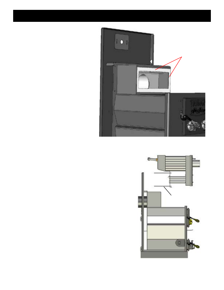
When re-installing the heat exchanger, inspect the gasket around the
furnace opening, and replace if necessary. (Figure A) Place the heat
exchanger in position and secure with the long bolts and nuts. Be sure the
gasket is compressed evenly.
Re-install the sheet metal by sliding the groove on the bottom of each side
panel over the steel lip on the furnace. The top sheet metal piece holds the
sides in place. The SF2600 front cover gets installed by angling the bottom
edge over the lip on the top of the firebox. The side edges must slide into
the grooves on each side and pushed in flush with the sides and top. This
front piece is held in place by the black ring which gets tightened around
the burner pipe. Do not over tighten as this will push the sheet metal in
too far.
Furnace Installation
Figure A
Figure b
Inspect Gasket prior to re-
installing heat exchanger.
(4) 12in. bolts, two on
each side, attach the heat
exchanger to the furnace.