Physical installation – Herrmidifier Co 707U-UK User Manual
Page 9
8
11. Before mounting the humidifier in its final position, carefully rotate the impeller assembly
by hand to ensure it rotates freely. Mount the humidifier on the wire mounting bracket with
the float and valve assembly connection facing the most convenient location, but providing
the least obstruction to traffic. Be sure that the water reservoir pan feet do not rest on the
wire bracket and that the water reservoir pan is level.
12. Locate the discharge hole on the outside wall. Mount the outside wall hole template using
the center of the pilot hole for reference. A pencil may also be used to find the previously
drilled pilot hole. When the outside wall hole template is secured, cut the hole in the
outside wall, using a saber saw or equivalent, for the discharge nozzle.
13. Measure the total thickness of the wall, not the stud thickness, but the distance between
the surfaces of the inside and outside walls.
14. The length of the discharge extension nozzle (provided) will be 2 5/8” long PLUS the total
wall thickness as determined in the previous step. Cut the extension nozzle to length on the
square end. The opposite end of the extension nozzle is angled to provide the correct fit
with the outside wall.
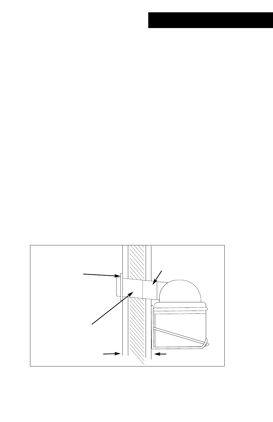
15. Fit the flexible connector sleeve onto the discharge dome and fasten securely with one (1)
hose clamp provided.
16. Insert the angle cut end of the extension discharge nozzle into the hole cut into the inside
wall, making sure the white line is pointed UP. Connect the extension discharge nozzle to
the discharge dome’s flexible connector sleeve. The angle cut end of the extension discharge
nozzle should be adjusted so that 5/8” of the tube extends past the outside wall. Secure in
position with one (1) hose clamp.
17. Install the cosmetic bezel onto the discharge side of the extension discharge nozzle. Making
sure that the bezel sits flat against the wall, 1/4” of the extension discharge nozzle should
extend past the bezel. This setup is necessary to prevent excessive condensation.
Physical installation
Connector sleeve
Inside wall
Outside wall
Discharge extension
nozzle
Cosmetic bezel