Assembly – Husqvarna 532 42 89-49 User Manual
Page 7
7
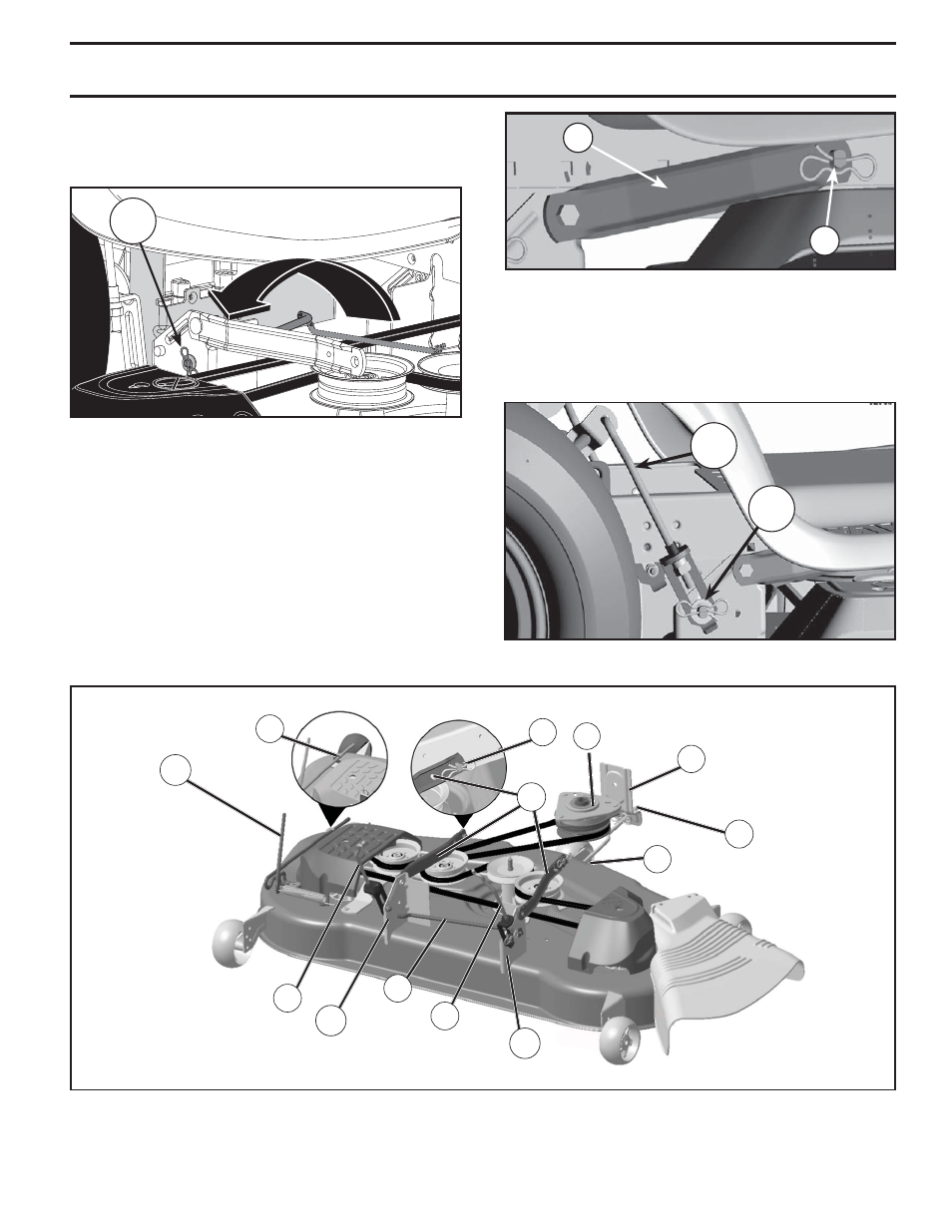
Fig. 10
B
F
M
C
S
E
K
D
L
D
A
C
H
D
Fig. 7
• Pivot bar towards you and insert other end of bar
into hole in rear mower bracket (D). Move mower
as needed to insert bar.
• Secure with washer and retainer spring as shown
•
ATTACH MOWER SIDE SUSPENSION ARMS (A) TO
CHASSIS - Position hole in arm over pin (B) on outside
of tractor chassis and secure with washer and retainer
spring.
•
Repeat on opposite side of tractor.
Fig. 8
A
B
•
ATTACH REAR LIFT LINKS (C) - Lift rear corner of
mower and position slot in link assembly over pin on
rear mower bracket (D) and secure with washer and
retainer spring.
•
Repeat on opposite side of tractor.
Fig. 9
D
C
ASSEMBLY
This manual is related to the following products: