Configuration, 1 configuration menus, See following pages for explanations) – Honeywell ZONEPRO TB6980 User Manual
Page 3: Repeat steps 3 and 4 for remaining items
TB6980/TB7980 62-0238 400-150-005-B 3/23/06 3/6
4. Configuration
4.1 Configuration Menus
(See following pages for explanations)
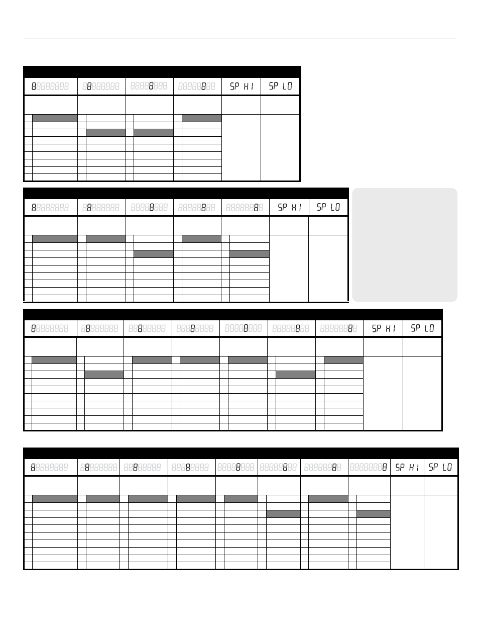
TB7980A model
Application
(section 4.2)
Default mode &
Output 1 type
(section 4.3.1)
NSB value
(section 5.5)
Output 1
min. opening
(section 4.3.2)
Maximum
setpoint
(section 4.6)
Minimum
setpoint
(section 4.6)
0 Internal sensor
0 Cool / 0-10V
1 1°C (2°F)
0 0%
Can be set
between 35°C
(95°F) and
’’minimum
setpoint + 1’’
Default value
is 35°C (95°F)
Can be set
between 10°C
(50°F) and
’’maximum
setpoint - 1’’
Default value
is 10°C (50°F)
1 Room
1 Heat / 0-10 V
2 2°C (4°F)
1 10%
2 Return
2 Cool / 2-10 V
3 3°C (6°F)
2 20%
3 Supply
3 Heat / 2-10 V
4 4°C (8°F)
3 30%
4 Auto changeover
5 5°C (10°F)
4 40%
5 Limited cooling
6 6°C (12°F)
5 50%
7 7°C (14°F)
8 8°C (16°F)
9 9°C (18°F)
TB6980A model
Application
(section 4.2)
Default mode
(section 4.3.1)
NSB value
(section 5.5)
Output 1
min. opening
(section 4.3.2)
Output 1
opening time
(section 4.3.3)
Maximum
setpoint
(section 4.6)
Minimum
setpoint
(section 4.6)
0 Internal sensor
0 Cool
1 1°C (2°F)
0 0%
0 80
Can be set
between 35°C
(95°F) and
’’minimum
setpoint + 1’’
Default value
is 35°C (95°F)
Can be set
between 10°C
(50°F) and
’’maximum
setpoint - 1’’
Default value
is 10°C (50°F)
1 Room
1 Heat
2 2°C (4°F)
1 10%
1 90
2 Return
3 3°C (6°F)
2 20%
2 100
3 Supply
4 4°C (8°F)
3 30%
3 110
4 Auto changeover
5 5°C (10°F)
4 40%
4 120
5 Limited cooling
6 6°C (12°F)
5 50%
5 130
7 7°C (14°F)
6 140
8 8°C (16°F)
7 150
9 9°C (18°F)
8 160
TB7980B model
Application
(section 4.2)
Default mode &
Output 1 type
(section 4.3.1)
Output 2 type
a
(section 4.4)
Output 3 type
(section 4.5)
Output 3
activation
(section 4.5)
NSB value
(section 5.5)
Output 1
min. opening
(section 4.3.2)
Maximum
setpoint
(section 4.6)
Minimum
setpoint
(section 4.6)
0 Internal sensor
0 Cool / 0-10V
0 Not used
0 Not used
0 100%
1 1°C (2°F)
0 0%
Can be set
between 35°C
(95°F) and
’’minimum
setpoint + 1’’
Default value
is 35°C (95°F)
Can be set
between 10°C
(50°F) and
’’maximum
setpoint - 1’’
Default value
is 10°C (50°F)
1 Room
1 Heat / 0-10 V
1 SSR 24 VAC
1 SSR 24 VAC
1 10%
2 2°C (4°F)
1 10%
2 Return
2 Cool / 2-10 V
2 N.C. Valve
2 N.C. Valve
2 20%
3 3°C (6°F)
2 20%
3 Supply
3 Heat / 2-10 V
3 N.O. Valve
3 N.O. Valve
3 30%
4 4°C (8°F)
3 30%
4 Auto changeover
4 Mech. relay
4 Mech. relay
4 40%
5 5°C (10°F)
4 40%
5 Limited cooling
5 SSR 3-32 V
5 Contact
5 50%
6 6°C (12°F)
5 50%
6 SCR 0-10 V
6 60%
7 7°C (14°F)
7 Act. 0-10 V
7 70%
8 8°C (16°F)
8 Act. / 2-10 V
8 80%
9 9°C (18°F)
9 90%
a.
If Output 2 type is set to 0-4, set the SW6 switch to Triac. If the output type is set to 5-8, set the switch to Analog (see section 4.7).
TB6980B model
Application
(section 4.2)
Default mode
(section 4.3.1)
Output 2 type
a
(section 4.4)
Output 3 type
(section 4.5)
Output 3
activation
(section 4.5)
NSB value
(section 5.5)
Output 1
min. opening
(section 4.3.2)
Output 1
opening time
(section 4.3.3)
Maximum
setpoint
(section 4.6)
Minimum
setpoint
(section 4.6)
0 Internal sensor
0 Cool
0 Not used
0 Not used
0 100%
1 1°C (2°F)
0 0%
0 80
Can be set
between
35°C (95°F)
and ’’min
setpoint + 1’’
Default
value is
35°C (95°F)
Can be set
between
10°C (50°F)
and ’’max
setpoint - 1’’
Default
value is
10°C (50°F)
1 Room
1 Heat
1 SSR 24 VAC
1 SSR 24 VAC
1 10%
2 2°C (4°F)
1 10%
1 90
2 Return
2 N.C. Valve
2 N.C. Valve
2 20%
3 3°C (6°F)
2 20%
2 100
3 Supply
3 N.O. Valve
3 N.O. Valve
3 30%
4 4°C (8°F)
3 30%
3 110
4 Auto changeover
4 Mech. relay
4 Mech. relay
4 40%
5 5°C (10°F)
4 40%
4 120
5 Limited cooling
5 SSR 3-32 V
5 Contact
5 50%
6 6°C (12°F)
5 50%
5 130
6 SCR 0-10 V
6 60%
7 7°C (14°F)
6 140
7 Act. 0-10 V
7 70%
8 8°C (16°F)
7 150
8 Act. / 2-10 V
8 80%
9 9°C (18°F)
8 160
9 90%
a.
If Output 2 type is set to 0-4, set the SW6 switch to Triac. If the output type is set to 5-8, set the switch to Analog (see section 4.7).
n
Remove the thermostat from its base and
set the SW2 switch to MENU.
o
Reinstall the thermostat. The thermostat is
now in configuration mode. The first digit
flashes to indicate that the first item of the
menu can now be modified.
p
To modify the setting, use the up/down
arrows. Refer to the adjacent tables.
q
Press Override to save the new setting and
go to the next item.
r
Repeat steps 3 and 4 for remaining items.
s
When the configuration is done, set the
SW2 switch back to NORMAL.
NOTE: Factory settings are inside the shaded cells.
ABBREVIATIONS
NSB - Night setback (number of degrees
the thermostat will be set back upon
receiving a setback signal)
SSR - Solid state relay (used with fast
cycling electric heaters, SSR's are a quiet
alternative to electromechanical relays.
They're typically included with electric
duct reheat equipment)
SCR - Silicon controlled rectifier (similar
to an SSR, SCR's are also quiet and
capable of switching very high current. If
used, they're usually included with the
equipment)
N.C. - Normally closed
N.O. - Normally open