0 front panel – gohastings.com POWERPOD 400 User Manual
Page 10
Page 10 of 42
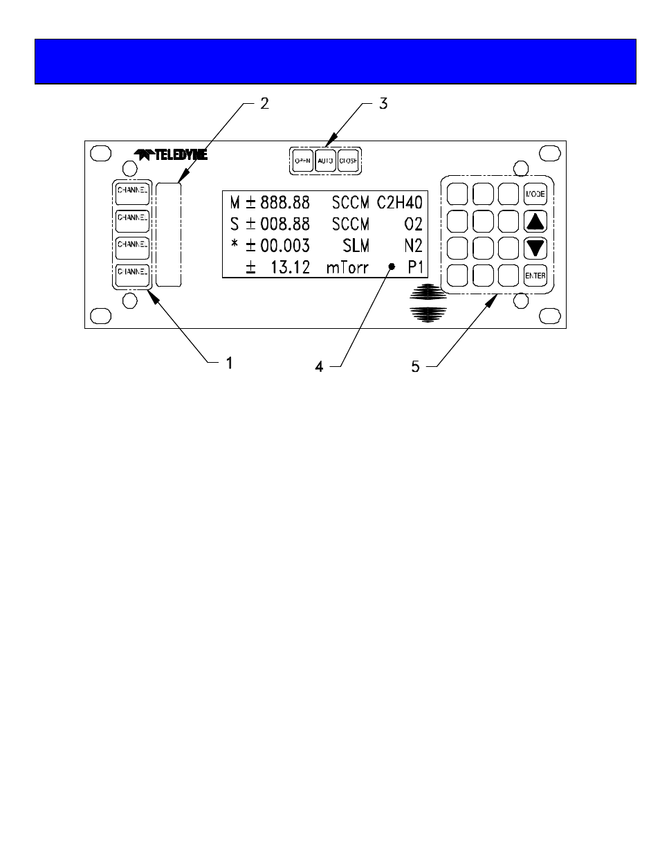
1.
CHANNEL NUMBER SELECT KEYS
Selects channel for editing. An asterisk (*) appears in the first column of the display to indicate that this is the channel to
be edited.
2.
OVERRIDE INDICATORS
Indicates when a channel’s command signal is overridden high (OPEN) or low (CLOSED).
3.
OVERRIDE KEYS
Override the command signal on the ACTIVE CHANNEL . OPEN sets control override (pin 8) to +15V. CLOSED
sets command to –15V. AUTO allows the user to set the command signal for normal operation. A channel must be
active before these keys can become operational.
4.
DISPLAY AREA
Column 1:
Reserved for displaying ACTIVE CHANNEL (*), MASTER channel (M), SLAVE (S) or
TOTAL (T).
Column 2:
Reserved for polarity indicator.
Col’s 3 – 8:
Signal monitor. Displays current input signal while in METER mode, AVERAGE while set
to average readings or TOTAL while in TOTALIZER mode.
Column 9:
Space
Col’s 10 – 14:
UNITS OF MEASURE display.
Column 15:
Space
Col’s 16 – 20:
GAS ID.
5.
KEYPAD
Use to enter SET POINTS or to modify the SETUP or CALIBRATION of control unit.
5.0 Front Panel
CLOSE
HASTINGS
OPEN
OPEN
CLOSE
OPEN
CLOSE
OPEN
CLOSE
1
4
3
2
7
1
4
0
9
3
6
8
2
5
.
400