Assembly and operation instructions (continued) – Harbor Freight Tools 95029 User Manual
Page 5
Page 5
SKU 95029
For technical questions, please call 1-800-444-3353
Assembly and Operation Instructions (continued)
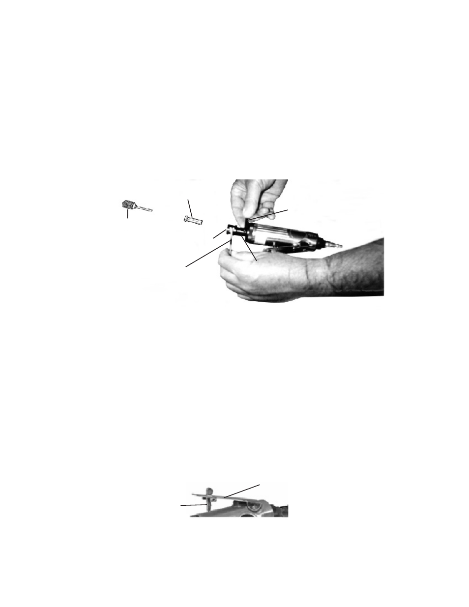
Figure C
Lever (14)
Lever Pin (15)
Note: The Composite Air Die Grinder is designed to be used with grinding attachments,
backing pads and sanding discs and other small attachments such as the grind-
ing drum shown in Figure B below.
To Operate the Die Grinder:
1.
WARNING: Prior to performing any assembly and/or adjustment procedures, make
sure the air supply hose (not included) is disconnected from the Die Grinder.
2.
WARNING: Always wear ANSI-approved safety goggles, a full face shield, and
hearing protection when operating the Die Grinder.
3.
Use the two Wrenches (30) to loosen the Collet Nut (29). (
See Figure B below.)
4. Insert the 1/4” diameter shank of a Grinding Accessory (not included) fully into the Col-
let (28). Then, firmly re-tighten the Collet Nut (29) to lock both the Collet and Grinding
Drum in place. (
See Figure B.)
5.
Connect the air supply hose to the Air Inlet (13). Turn on the air compressor and set
its regulator to the recommended 90 PSI for the Die Grinder.
6.
In order to keep the air supply hose out of the way, hang it over your shoulder.
7.
IMPORTANT! Grip the Die Grinder firmly with both hands.
8.
Trip the Lever Pin (15) with your finger. Then slowly apply hand pressure to the Lever
(14) until the desired speed is obtained. (
See Figure C.) NOTE: The Die Grinder always
turns the Grinding Drum clockwise (reference: while holding the tool as you would when
operating it).
Wrench (30)
Collet Nut
(29)
Spindle (25)
Figure B
Wrench (30)
Collet (28)
Grinding Drum
(not included)