Honeywell Q674A-E User Manual
Page 8
8
60-1165—6
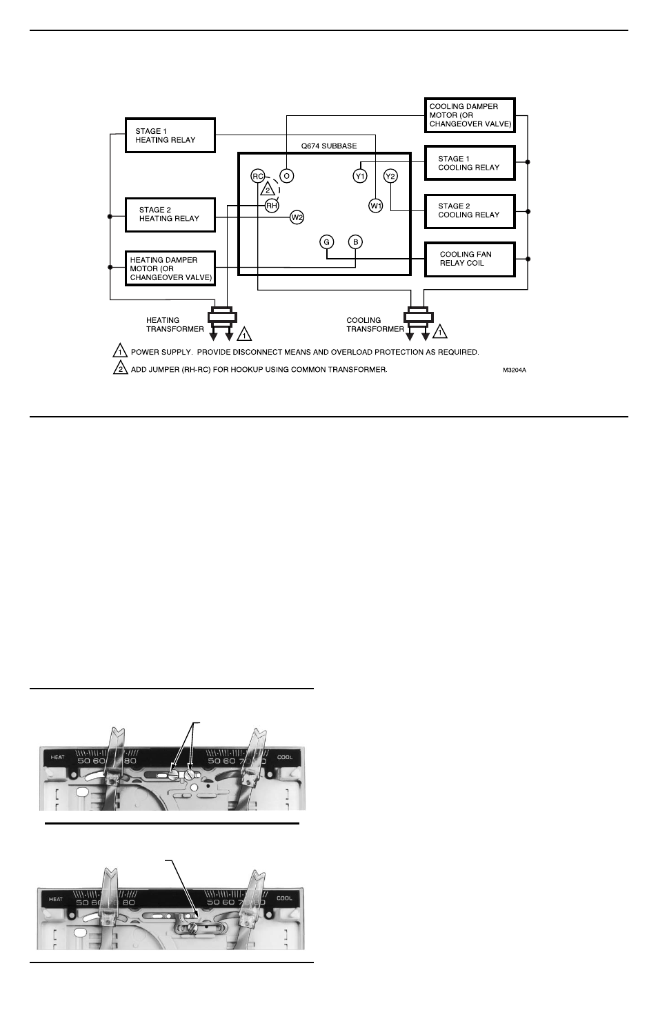
Fig. 16—Typical Q674 terminal designations. The thermostat and subbase used determines the number
of system components controlled.
TEMPERATURE LEVER STOPS
Some thermostats have factory-installed temperature
lever locking screws (Fig. 17) and/or stop brackets
(Fig. 18). Use these only if the HEAT and COOL tempera-
ture set point lever ranges are to be restricted. If the compo-
nents are factory-installed, see the specific section below
for the adjustment procedure.
If a temperature range restriction is required and the
locking components are not factory-installed, it is neces-
sary to order a 4074ECK Envelope Assembly. This enve-
lope includes two stop brackets, one brass insert and one
bracket mounting screw for restricting the adjustable range
of the HEAT and COOL set point levers. Also, the enve-
lope includes two screws with plastic insulated heads for
locking the set point control levers in position. If the
components are to be used, see the specific section below
for the installation procedure.
Fig. 17—Location of lever locking screws.
Fig. 18—Location of lever stop brackets.
INSTALL AND ADJUST LOCKING LEVER
SCREWS
The two screws with insulated heads should be used
only if the HEAT and COOL levers are to be locked in
place at a specific temperature control point. Do not use
standard screws that provide metal-to-metal contact with
the lever brackets.
To install:
1. Refer to Fig. 20 for screw hole locations.
2. Install the two screws with insulated heads in the
indicated holes. Do not overtighten screws.
3. Set the HEAT lever and the COOL lever at desired
temperature control points.
4. Firmly tighten both screws.
INSTALL AND ADJUST STOP BRACKETS
Install the stop brackets only if there is a need to restrict
the adjustable range of the heating and cooling temperature
set point levers.
To install:
1. Turn to the back of the T874 Thermostat. Locate the
hole for the brass insert in the plastic base below the LED
window. See Fig. 19.
2. Push the brass insert into the hole with your finger.
3. Turn to the front of the T874 Thermostat.
4. Place the two stop brackets in position with the tabs
in the slot between the HEAT and COOL levers. See
Fig. 20.
5. Insert the mounting screw into the two slots in the
stop brackets and attach to the brass insert. Tighten the
screw to pull the brass insert into the back of the thermostat.
6. Loosen the mounting screw enough so the stop brack-
ets can slide for adjustment.
7. Move the HEAT and COOL set point levers to the
maximum temperature that is desired.
8. Slide the stop brackets until one rests against the
HEAT lever and the other against the COOL lever.
LEVER LOCKING SCREWS
M18680
LEVER STOP BRACKETS
M18681