6000g-ipi – Hearth and Home Technologies 6000G-IPI User Manual
Page 72
Heat & Glo • 6000G, 6000G-IPI • 2103-900 Rev. O • 12/08
72
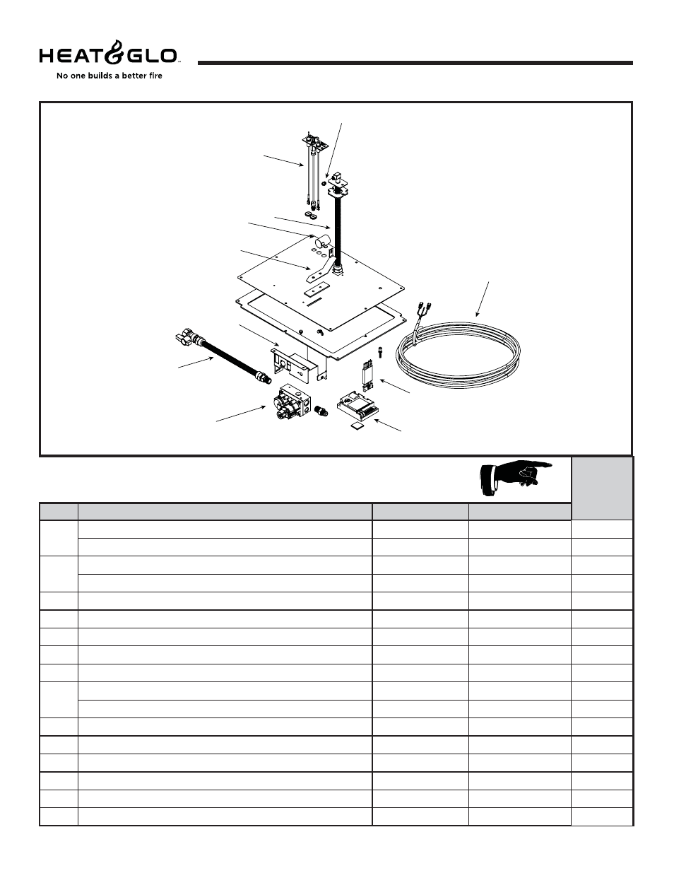
Service Parts
Valve Assembly Diagram/ Parts List
IMPORTANT: THIS IS DATED INFORMATION. When requesting service or replacement parts for your
appliance please provide model number and serial number. All parts listed in this manual may be ordered
from an authorized dealer.
Stocked at
Depot
ITEM
DESCRIPTION
COMMENTS
PART NUMBER
1
Orifi ce, NG (#37C)
582-837
Y
Orifi ce, LP (#52C)
582-852
Y
2
Pilot Assembly, NG
2090-012
Y
Pilot Assembly, LP
2090-013
Y
3
Flex Tube Assembly
383-302A
Y
4
Shutter Sleeve
2026-130
Y
5
Shutter Bracket Assembly
2026-017
Y
6
Valve Bracket
2118-104
7
Flex Ball Valve Assembly
302-320A
Y
8
Valve, NG
750-500
Y
Valve, LP
750-501
Y
9
Module Wire Assembly
593-590A
Y
10
Control Module
593-592
Y
11
Thermostat Wire Assembly
2045-024
Y
3V Transformer
593-593A
Y
Remote Wire Assembly
2103-013
Y
Battery Pack
593-594A
Y
2
3
7
10
9
1
5
6
8
4
11
Beginning Manufacturing Date: May 2006
Ending Manufacturing Date: ______
6000G-IPI
Intermittent Pilot Ignition
Valve Assembly