Harman-Kardon AVR 254 User Manual
Page 13
13
13
13
13
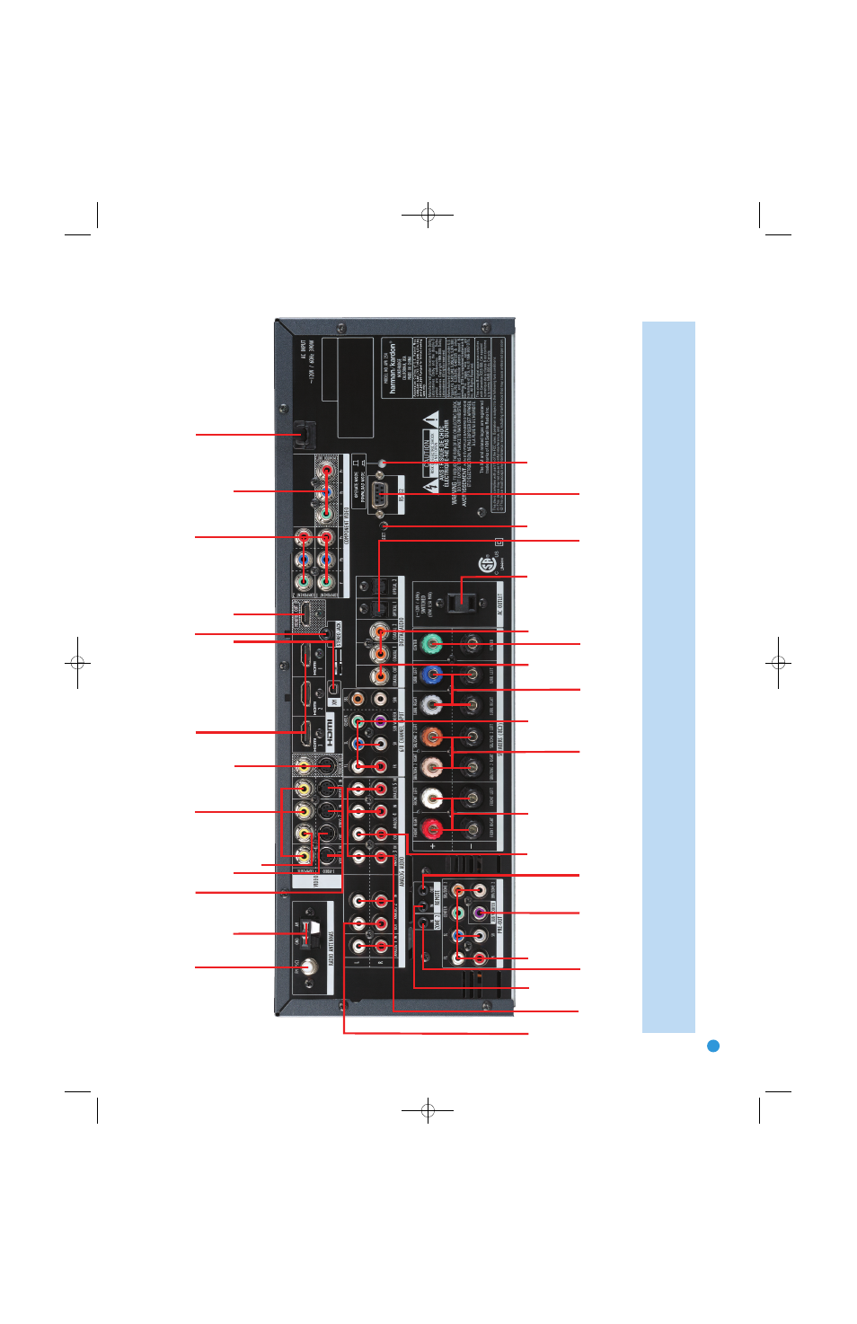
FM Antenna
XM
Antenna
AM Antenna
S-Video 2
Output
Composite 2
Output
Composite
1,
2 and 3
S-Video
1,
2 and 3
Video
Monitor
Outputs
HDMI
1,
2 and 3
AC P
o
wer
Cord
Component
1 and 2
Stereo Jack
HDMI
Monitor
Output
Component Video
Monitor Outputs
Subwoofer
Output
Preamp
Outputs
Front Speaker
Outputs
Surround
Speaker
Outputs
6-/8-
Channel
Inputs
Surround
Back/Zone 2
Speaker Outputs
Center Speaker
Outputs
Switched AC
Accessor
y
Outlet
RS-232
Reset
RS-232
Serial P
ort
Coaxial
Digital
Audio
Output
Coaxial
1 and 2
Digital
Audio
Optical 1 and 2
Digital Audio
Analog 1-5
Inputs
Zone 2
IR Input
Remote
IR Input
Remote
IR Output
Analog 2
Outputs
Analog 4
Outputs
RS-232
Mode
NOTE:
To make it easier to follow the instructions throughout the manual that refer to this illustration,
a copy of this page may be d
ownloaded from the Product Support section at
www
.har
mankardon.com.
All connectors are inputs except as indicated.
AVR254om.qxd 3/28/08 12:45 PM Page 13
- 660 (42 pages)
- AVR 255 (58 pages)
- AVR 165 (42 pages)
- AVR 70 (26 pages)
- 210 (52 pages)
- AVR1550 (30 pages)
- AVR 520 (56 pages)
- AVR 360 (28 pages)
- AVR360 (38 pages)
- AVR 110 (56 pages)
- AVR 3600 (66 pages)
- AVR 5000 (58 pages)
- AVR 3000 (52 pages)
- AVR507 (48 pages)
- AVR 660 (28 pages)
- AVR 430 (52 pages)
- KARDON AVR 360 (28 pages)
- 231 (11 pages)
- AVR 145 (63 pages)
- AVR 510 (56 pages)
- AVR 3650 (61 pages)
- Stereo Amplifier (2 pages)
- AVR 240 (64 pages)
- Signature Series (12 pages)
- AVR 1565 (2 pages)
- AVR5 (40 pages)
- PA5800 (12 pages)
- 347 (64 pages)
- DVD47 (40 pages)
- AVR 300 (40 pages)
- DVD 37 (40 pages)
- AVR 146 (60 pages)
- AVR 2650 (62 pages)
- AVR 247 (76 pages)
- AVR 2000 (48 pages)
- AVR 147 (52 pages)
- GB4 (40 pages)
- AVR 310 (54 pages)
- HA160-0004-A (72 pages)
- AVR 135 (42 pages)
- AVR 245 (72 pages)
- AVR 245 (1 page)
- HK 3380 (20 pages)
- AVR 160 (48 pages)
- AVR 260 (54 pages)