Appendix – HP 2209T User Manual
Page 25
20
Appendix
Connector pin assignment
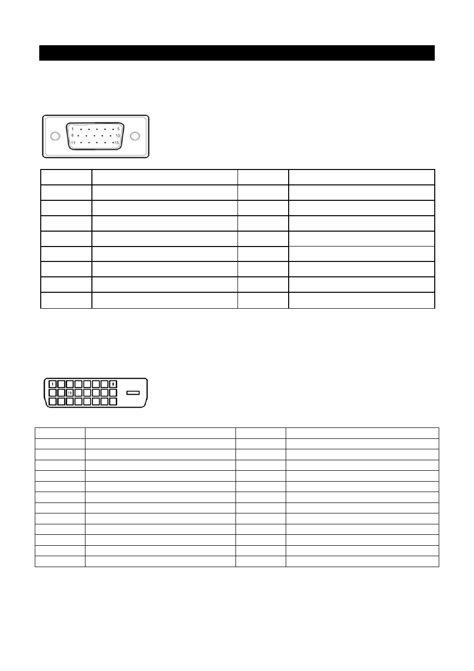
15 pin color display signal cable:
PIN
No. Description PIN
No. Description
1.
Red
9.
+5V
2.
Green
10.
Logic ground
3.
Blue
11.
Monitor ground
4.
Monitor ground
12.
DDC-serial data
5.
DDC-return
13.
H-sync
6.
R-ground
14.
V-sync
7.
G-ground
15.
DDC-serial time sequence
8.
B-ground
24 pin
DVD-D display signal cable:
Pin
No. Description Pin
No. Description
1
TMDS Data 2 -
13
TMDS Data 3 +
2
TMDS Data 2 +
14
+3.3/+5V Power (from PC)
3
TMDS Data 2 / 4 Shield
15
Ground (Return for +5V)
4
TMDS Data 4 -
16
Hot Plug Detect
5
TMDS Data 4 +
17
TMDS Data 0 -
6
DDC Clock
18
TMDS Data 0 +
7
DDC Data
19
TMDS Data 0 / 5 Shield
8
No Connect
20
TMDS Data 5 -
9
TMDS Data 1 -
21
TMDS Data 5 +
10
TMDS Data 1 +
22
TMDS Clock Shield
11
TMDS Data 1 / 3 Shield
23
TMDS Clock +
12
TMDS Data 3 -
24
TMDS Clock -
- 2311CM (47 pages)
- 1706 (60 pages)
- mx705e 17 inch CRT Monitor (44 pages)
- 2010i 20-inch Diagonal LCD Monitor (49 pages)
- ZR30w 30-inch S-IPS LCD Monitor (34 pages)
- 2710 (4 pages)
- w2408 (3 pages)
- B160L (256 pages)
- Compaq TFT 2025 (36 pages)
- 1506 (60 pages)
- Compaq LA2405wg (5 pages)
- 20/700 (219 pages)
- Workstation P9615X#xxx (7 pages)
- 15-inchhp55 (17 pages)
- B6191-90029 (140 pages)
- 1825 (32 pages)
- 55HP (17 pages)
- Pavilion v52 15 inch Monitor (32 pages)
- w1858 18.5-inch LCD Monitor (68 pages)
- Monitor MPRII 17 pollici HP 71 (16 pages)
- w2207 22-inch Widescreen LCD Monitor (56 pages)
- ЖК-монитор HP 2159m 215 inch Full HD (1 page)
- L1506x 15-inch Non-Touch Monitor (37 pages)
- L1710 17-inch LCD Monitor (67 pages)
- L1710 17-inch LCD Monitor (63 pages)
- 55 15 inch color Monitor (16 pages)
- vs17x 17 inch LCD Monitor (78 pages)
- Pantalla LED interactiva de 46.96 pulgadas HP LD4745tm Digital Signage (117 pages)
- vs19x 19 inch LCD Monitor (80 pages)
- Pantalla LED de 55 pulgadas HP LD5535 Digital Signage (111 pages)
- LD4745tm 46.96-inch Interactive LED Digital Signage Display (39 pages)
- LD4730G 47-inch Micro-Bezel Video Wall Display with Protective Glass (72 pages)
- LD4730G 47-inch Micro-Bezel Video Wall Display with Protective Glass (42 pages)
- Z Display Z22i 21.5-inch IPS LED Backlit Monitor (28 pages)
- Compaq LA2205wg 22-inch Widescreen LCD Monitor (28 pages)
- w2228k 22-inch LCD Monitor (62 pages)
- ZR30w 30-inch S-IPS LCD Monitor (34 pages)
- v216 21.6 inch LCD Monitor (30 pages)
- L1950 19-inch LCD Monitor (49 pages)
- L1710 17-inch LCD Monitor (55 pages)
- L1706 17-inch LCD Monitor (24 pages)
- v185ws 18.5-inch Widescreen LCD Monitor (31 pages)
- v185es 18.5-inch Widescreen LCD Monitor (30 pages)
- LE1901wi 19-inch Widescreen LCD Monitor (55 pages)