Tools included parts included, Pre-assembly assembly step 1 – Horizon Fitness FS 50 User Manual
Page 4
INTRODUCTION
IMPORT
ANT
PRECAUTIONS
ASSEMBL
Y
BEFORE
YOU
BEGIN
CONDITIONING
GUIDELINES
TROUBLESHOOTING
&
MAINTENANCE
LIMITED
W
ARRANTY
INTRODUCTION
IMPORT
ANT
PRECAUTIONS
ASSEMBL
Y
BEFORE YOU
BEGIN
CONDITIONING GUIDELINES
TROUBLESHOOTING &
MAINTENANCE
LIMITED WARRANTY
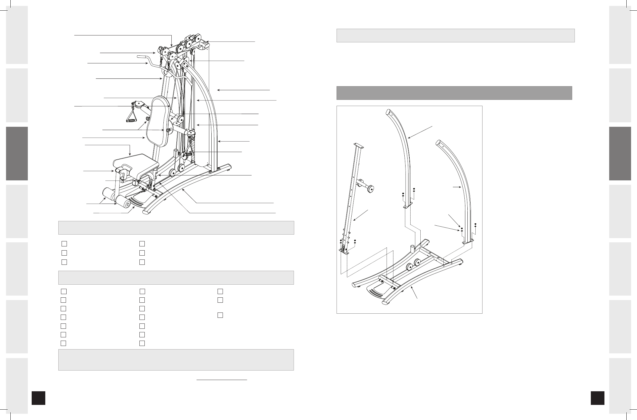
TOOLS INCLUDED
PARTS INCLUDED
1 Seat Assembly Safety Pin
2 Foam Rollers
1 Seat Back Cushion
1 Main Base Frame
1 Main Support Frame (Right)
1 Main Support Frame (Left)
1 Radial Arm Assembly
1 Center Upright
1 Seat Assembly
3 Weight Shields
2 Guide Rods
1 Weight Selection Pin
1 Upper Pulley Bracket
1 Dual Floating Pulley Bracket
1 Single Floating Pulley Bracket
1 Upper Pulley Assembly
(Multiple Pulleys)
3 Cables
LAT PULLDOWN BAR
LAT BAR BRACKET ASSEMBLY
MAIN SUPPORT FRAME (RIGHT)
CENTER SUPPORT FRAME
CABLE “C”
RADIAL ARM ADJUSTMENT PIN
SEAT BACK PAD
SEAT BOTTOM PAD
SEAT ASSEMBLY
SEAT HEIGHT ADJUSTMENT KNOB
FOAM LEGROLLERS
ADJUSTABLE FOOTPLATE
CABLE “B”
BASE FRAME
SEAT ASSEMBLY SAFETY PIN
MAIN SUPPORT FRAME (LEFT)
SINGLE FLOATING PULLEY BRACKET
WEIGHT SELECTION PIN
WEIGHT SHIELD
DUAL FLOATING PULLEY BRACKET
GUIDE ROD
UPPER PULLEY ASSEMBLY
RADIAL ARM ASSEMBLY
CABLE “A”
If you have questions or if there are any missing parts, contact Customer Tech Support.
Contact information is located on the back panel of this manual.
For a complete exploded diagram, visit us at www.horizonfitness.com
Screwdriver
19 mm Flat Wrench
13 mm/17 mm Flat Wrench
4 mm Allen Wrench
6 mm Allen Wrench
8 mm Allen Wrench
NOTE:
During each assembly step, ensure that ALL nuts and bolts are in place and partially threaded in before
completely tightening any ONE bolt. NOTE: A light application of grease may aid in the installation of hardware.
Any grease, such as lithium bike grease is recommended.
PRE-ASSEMBLY
ASSEMBLY STEP 1
BASE FRAME
MAIN SUPPORT
FRAME (RIGHT)
MAIN SUPPORT
FRAME (LEFT)
NYLON NUT (C)
FLAT WASHER (B)
CENTER SUPPORT
FRAME
Place BASE FRAME on floor in
desired location.
Remove 6 NYLON NUTS (C)
and 6 FLAT WASHERS (B) from
BASE FRAME.
Attach RIGHT MAIN SUPPORT
FRAME to right side of BASE
FRAME using 2 BOLTS (A),
2 FLAT WASHERS (B) and 2
NYLON NUTS (C).
Repeat on other side.
Attach CENTER SUPPORT
FRAME to BASE FRAME using
2 BOLTS (A), 2 FLAT WASHERS
(B) and 2 NYLON NUTS (C).
A
B
C
D
E
FS 50 rev 1.0.indd 6-7
8/20/07 11:57:41 AM