Hubbell Electric Heater Company J User Manual
Page 12
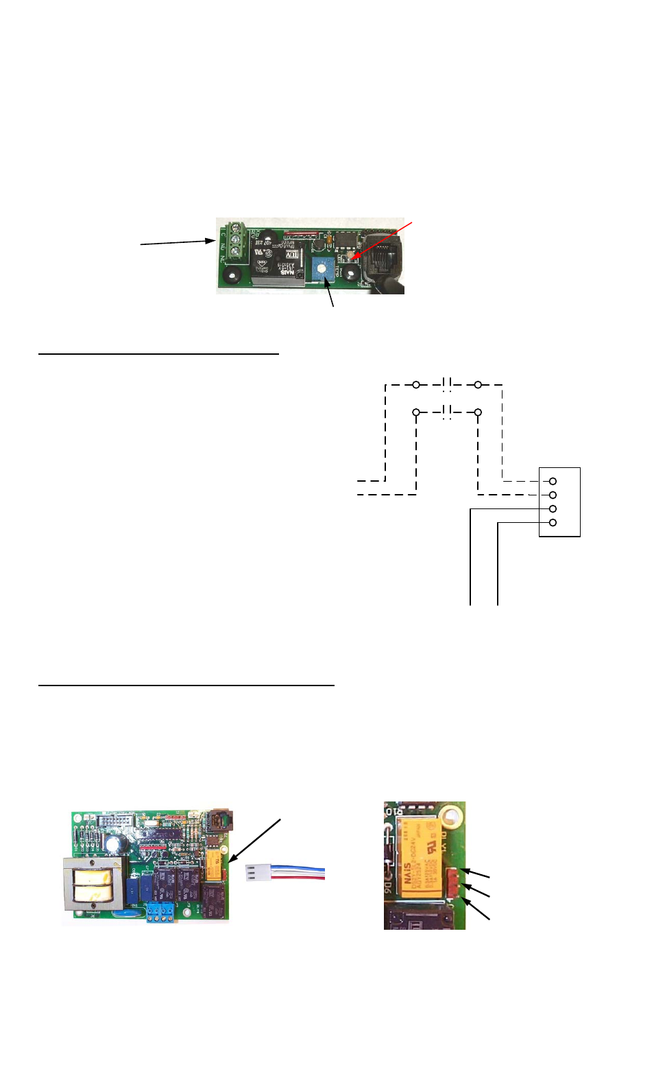
3. To set the XB1 setpoint, turn the potentiometer clockwise for a higher setpoint and
counter-clockwise for a lower setpoint. The range is adjustable between 150°F and
180°F.
4. Make connections as required to the relay terminal block. When the temperature drops
below the XB1 setpoint the relay is open between Normally Open (NO) and Common
(C) and the LED will flash green. When the temperature is above the XB1 setpoint the
relay is closed between NO and C and the LED will be solid green. Use NO and C for
low temperature interlock or high temperature alarm. Use Normally Closed (NC) and C
for low temperature alarm. A red LED indicates an error.
LED
Relay
Terminal Block
12
Temperature Adjustment Potentiometer
FOR REMOTE ON/OFF CONTROL
To remotely control the On / Off
operation of the heater, it is
recommended that a DPST
switch or relay (by others) be
used to break both power legs
(white and black wires)
connected to the top two
terminals of the J5 connector on
the control board. See diagram
at right.
Use a NC (Normally Closed)
relay to turn the booster ON
when energizing the relay coil
or to turn the booster OFF whe
de-energizing the relay coil.
n
Use a NO (Normally Open) relay to turn the booster OFF when energizing the relay coil or
to turn the booster ON when de-energizing the relay coil.
OPTIONAL REMOTE ALARM CONTACTS
1. If desired, the control board can be wired to a remote alarm to indicate a reset fault
condition. These fault conditions include over-temperature, no probe, and low water
(when the configuration is set to manual reset).
2. This alarm can be wired to the J4 connector on the control board as shown below. To
facilitate this installation, an optional adapter, Hubbell P/N PLUG ADAPTER J4, can
be purchased to provide wire connections.
J4 Connector
Note: Rating (resistive)
Max. Switching Power:
60W, 62.5VA
Max. Switching Voltage:
220VDC, 250VAC
Max. Switching Current: 2A
Max. Carrying Current: 3A
PLUG ADAPTER J4
Wiring by
Customer
Remote Relay by Customer
1
2
3
4
Controller J5 Connector
Red Wire to
Contactor #2
Wiring from Contactor,
Power Distribution Block,
or Transformer
Yellow Wire to
Contactor #1
Note: Rating (resistive):
Max.: 5A @ 120VAC
5A @ 24VDC
Common
(NO)
(NC)