Assembly (continued) – Harbor Freight Tools 91840 User Manual
Page 5
Page 5
For replacement parts, please call 1-800-444-3353.
SKUs
91839, 91840
& 9199
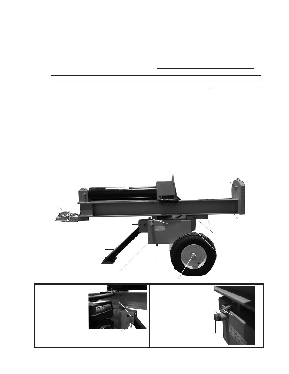
Hex Head Nut (17) is attached to Hex Head Bolt (16)
Assembly (continued)
Connecting the Rail Assembly (2) to the Oil Tank Assembly (10B)
Insert the Front Leg Assembly (11) into the bracket on the Oil Tank Assembly (10B).
Insert the remaining Hex Head Bolt (16) through the hole in the middle of the bracket
of the Oil Tank Assembly (10B). Secure it with a Hex Head Nut (17). Refer to the
Hex Head Nut (17) attached to the Hex Head Bolt (16) at the top of the Front Leg
Assembly (11) in
Figure 1 below. note: When travelling, remove the Push Pin
(26) and Hair Pin Clip (29) and lift the Front Leg Assembly up so that it is parallel to
the Rail Assembly (2). Then, replace the Push Pin (26) and Hair Pin Clip (29) into the
Horizontal Transport Hole shown just above the Oil Plug (37), in
FigureS 1 and 2.
To connect the Rail Assembly (2) to the Oil Tank Assembly (10B), insert a Hex Head
Bolt (16) into the middle hole of the “L” shaped bracket on the Oil Tank Assembly
(10B). Secure it with a Hex Head Nut (17). Refer to the Hex Head Nut (17) attached
to the Hex Head Bolt (16) just above the tire in
Figure 1 below. Insert the Push
Pin (26) through the hole, as shown in
Figure 3.
In
FigureS 1 and 2, the Rail Assembly (2) is shown in Horizontal mode for opera-
tion and travel (as mentioned above, the Front Leg Assembly (11) must be secured
up in the horizontal position when travelling). For vertical operation see page 6.
1.
2.
3.
Rail Assembly ()
Oil Tank (10B)
Oil Plug (37)
with air inlet hole
Wheel Cap (61)
FIGuRE 1
Safety Chain
with Hook (4)
Hitch Coupler (9)
Front Leg Assembly (11)
Oil Removal Plug
Push Pin (6) and
Hair Pin Clip (9
)
Horizontal transport hole
Place Log Here
Cylinder (1)
Hex Head Nut (17) is
attached to Hex Head Bolt
(16)
Vertical position
locking hole
FIGuRE 2
FIGuRE 3
Push Pin (6)
Oil Plug (37)
with air inlet ho
le
Close-up of Push Pin (6) securing the
Front Leg Assembly (11) to the bracket
on the Oil Tank Assembly (10B).
Second Push Pin (6) secures
Rail Assembly (), and is removed
for vertical log splitting.
Horizontal transport hole
Air Inlet Hole
Slide Assembly (3)
Base
Vertical Position Hole
Push Pin (6)