Figure 3-3, Figure 3-4 – Emerson 2400S User Manual
Page 18
14
Micro Motion
®
Model 2400S Transmitters
I/O Wiring – Model 2400S Analog Transmitters
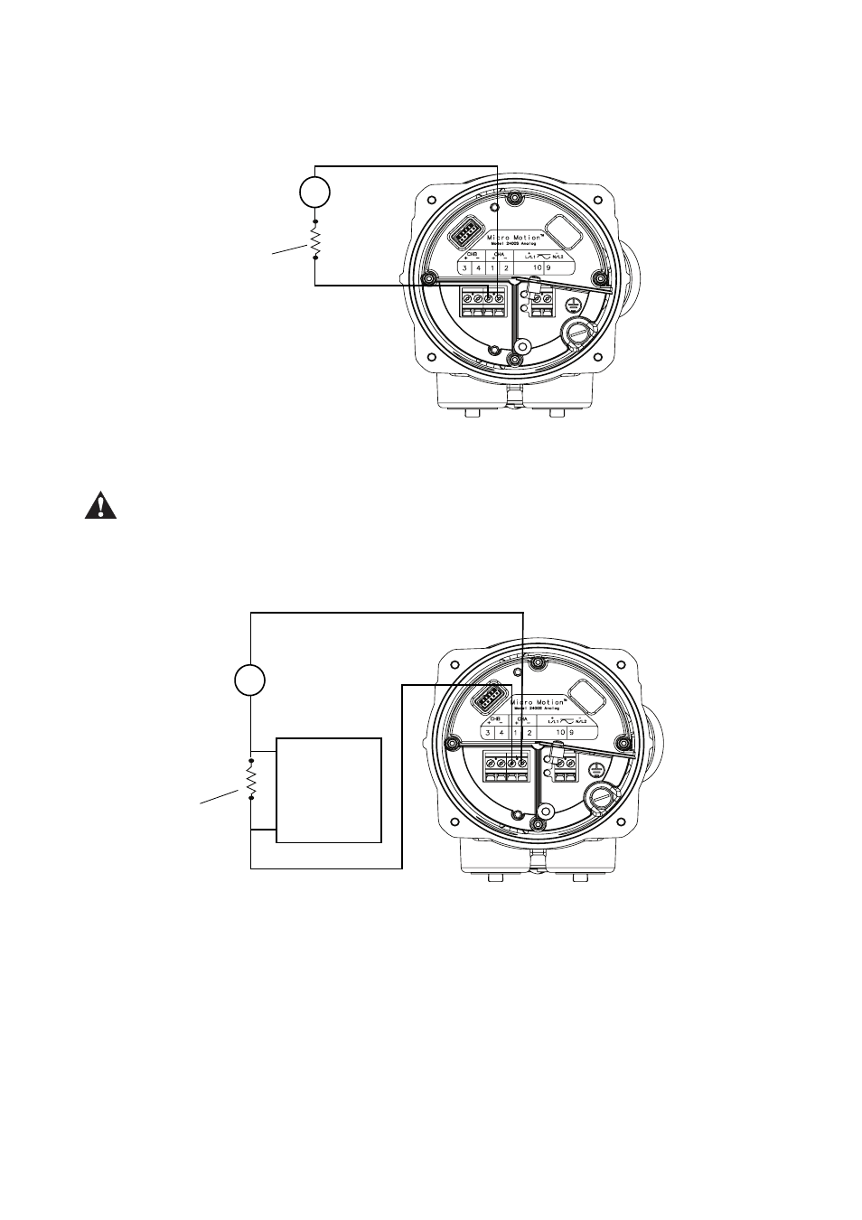
Figure 3-3
Basic mA output wiring – External power
Excessive current will damage the transmitter. Do not exceed 30 VDC input. Terminal current must be
less than 500 mA.
Figure 3-4
HART/analog single-loop wiring – External power
Note: See Figure 3-5 for voltage and
resistance values.
VDC
R
load
–
+
+
–
Note: See Figure 3-5 for voltage and resistance values.
VDC
R
load
(250–600 Ohm
resistance)
–
+
+
HART-
compatible host
or controller
–