Extron electronic P/N 68-424-02 User Manual
Page 3
Extron • System 4
xi
xi
xi
xi
xi
Switcher Series • User’s Manual • P/N 68-424-02 Rev. D
Configuration and Connections
Epson Installation
Page 3
6. Connect the Epson Comm Adapter’s 9-pin female connector to the 9-pin male
connector of the projector cable. Connect the other end of the Comm Adapter to
the Communications Extension cable (CC-50’ or CC-100’).
7. Plug the 15-pin HD connector of the Communications Extension cable into the
PJ Comm port on the System 4
xi
.
______ Secure all of the connector screws.
8. Plug the (4 or 5) BNC connectors from one end of the (user-supplied) RGBS/HV
cable onto the System 4
xi
output and those on the other end onto the matching
BNCs on the Epson 5300/7300 connector panel.
9. Power on the System 4
xi
and the projector.
10. Press the projector’s Menu button. From the projector display, select Options
and enter this selection.
11. Select Mouse/Com 1, then select BNC Format RGB and enter this selection.
_ When the projector and switcher are communicating with each other, there will be a delay of
30 to 60 seconds when powering the projector on/off using the System 4
xi
. While waiting for
the projector to power on, the message “ Pls Wait PRJ Dwn” will display on the System 4
xi
’s
LCD
System 4
xi
xi
xi
xi
xi
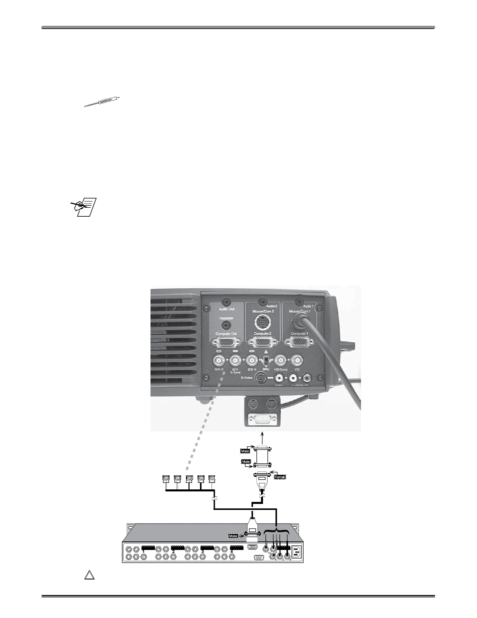
Series – Epson 5300/7300 Projector Connections
Use the illustration below as a guide when connecting the System 4
xi
to an
Epson 5300/7300 projector. Refer to Epson documentation to continue the
installation.
____________ In a rack mount, do NOT allow the weight of the cables to be supported by the
System 4
xi
. See page 2-5 for cabling guidelines.
9-Pin
Comm Adapter
26-484-01
"I"
CC 50'
3, 4 or 5 BNC
15-Pin
9-Pin
"I"