Front panel adjustments, Mounting the optional aap device – Extron electronic RGB 580xi User Manual
Page 11
RGB 580xi • Installation and Setup
RGB 580xi • Installation and Setup
Installation and Setup, cont’d
2-11
passes through long cables. Set the level at the maximum
setting for cable lengths over 500 feet for all computer
signals of 15 kHz to 135 kHz.
2.
Peaking control
— The Video Output Peaking control
affects the sharpness of a picture. Increased peaking can
compensate for detail (mid- and high-frequency) loss from
low bandwidth system components or capacitance in long
cables. The minimum setting (at the counterclockwise
limit) provides no peaking. The maximum setting (at the
clockwise limit) provides 100% peaking. Adjust this
control while viewing the displayed image to obtain the
optimum picture sharpness.
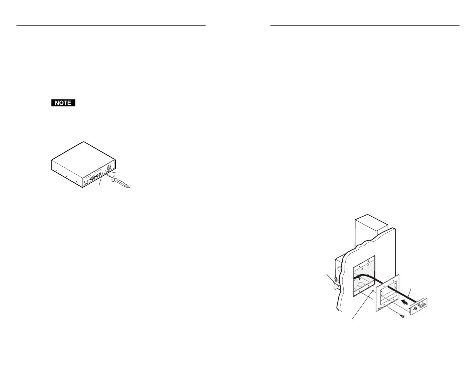
Mounting the Optional AAP Device
Extron’s various RGB 580xi AAP double-space devices may be
mounted to any Extron product that has an AAP faceplate, or to
an Extron AAP wallplate. See appendix A for AAP device part
numbers. The AAP device should be cabled before it is attached
to a faceplate or wallplate (see “Cabling the AAP Device Rear
Connectors” in this chapter). The screws needed for installing
an AAP device are built into its front panel, so no additional
screws are needed.
1.
Insert the AAP’s screws through the holes in the AAP
faceplate or the AAP wallplate. Secure the AAP device to
the faceplate or wallplate with the provided captive
washers and #4-40 nuts.
Example of mounting an AAP device to a wallplate
Cable
Cable
Clamp
RGB 580xi SI AAP
AAP 102
AAP
102
#4-40 Nut w/ Captive
Washer
RGB 5
80xi
SI AAP
CO
MPUTER
AUD
IO
H S
HIF
T
INPUT
SELECT
Front Panel Adjustments
Video signals passing through long cable runs (over 125 feet)
can decrease in strength, creating signal loss. The longer the
cable, the greater the cable resistance and capacitance, and the
greater the level and peaking adjustments that will be required
to compensate for the resultant signal loss. These adjustments
change the level and peaking of the output signal to compensate
for capacitance caused by up to 1000 feet (304.8 meters) of
Extron SHR cable.
If the displayed image is too bright or too dark, try
changing the level setting. If the edges of the displayed
image seem to exceed their boundaries, or if thin lines
and sharp edges look thick and fuzzy, try changing the
peaking setting. See the illustration below.
SO
G
SE
RR
DD
SP
V-S
YN
C W
ID
TH
NE
G S
YN
C
CO
MP
S
YN
C
INP
UTS
RGB 580
xi
ANALO
G
AUDIO
CO
NTR
OL
VID
EO
OU
TP
UT
LEVEL
A
B
C
D
E
PE
AK
ING
Level
Peaking
1.
Level adjustment control
— The Video Output Level
control alters the brightness of the displayed image. To
adjust the video output level, view the display while using
a small, flat-blade screwdriver to rotate this one-turn
potentiometer. You can judge the adjustment visually by
looking at the display.
If the interface receives a typical (0.7 volts p-p) analog
computer video input, the output is as follows:
•
At the minimum level setting (the counterclockwise
limit of this control), the interface outputs video at
0.5 volts p-p.
•
Unity level is 0.7 volts p-p, the same as the input
signal. Set the control to approximately one-half turn
between the minimum and maximum level settings
to output unity level video.
•
At the maximum level setting (the clockwise limit of
this control), the interface outputs video at
1.45 volts p-p.
Select a level setting of 0.7 volts or above to compensate
for the decrease in signal level that occurs when the signal
2-10