Edelbrock 2802 User Manual
Page 2
Part #2801-2806, 28001-28004 & 28081- 28084
Rev. 11/10 - AJ/mc
2 of 2
©2010 Edelbrock LLC
Brochure #63-0339
1.
Make sure the cylinder head intake flanges and the engine block end seal surfaces are fully cleaned prior to installation.
2.
Apply Edelbrock Gasgacinch sealant PN 9300 to both cylinder head flanges and to the cylinder head side of the gaskets, allow to air dry,
and attach the intake gaskets.
3.
Do not use cork or rubber end seals. Use RTV silicone sealer instead. Apply a ¼" high bead across each block end seal surface,
overlapping the intake gasket at the four corners. This method will eliminate end seal slippage.
4.
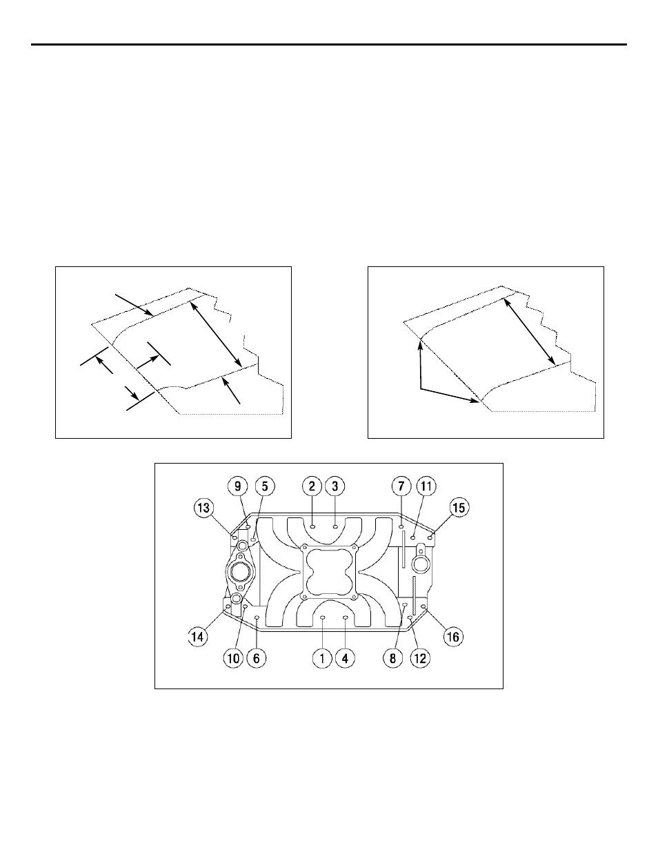
Install the intake manifold and hold-down bolts. Torque the manifold bolts to 25 ft/lbs in small, even steps, following the factory
recommended torque sequence
(See Figure 3). If you cannot fit a torque wrench on some of the bolts, use a small box end wrench
to avoid over tightening.
NOTE: Check bolt clearance near the water crossover. Minimal clearancing of the water crossover may be required for socket
or wrench clearance with a standard hex bolt.
Edelbrock LLC • 2700 California St. • Torrance, CA 90503
Tech-Line: 1-800-416-8628 • Office Line: 310-781-2222
INSTALLATION PROCEDURE
Figure 3 - Manifold Bolt Torque Sequence
Torque Bolts to 25 ft/lbs.
Stock Height
Matched
to Head
Figure 1
Figure 2
Stock Height
1”-2” Back
From Exit
Roof
Floor
Stock Height