Installation, Start-up, Trouble shooting & maintenance – Elkay ERS1-1D User Manual
Page 2
96703C (Rev. G - 5/99)
ELKAY MANUFACTURING COMPANY - 2222 CAMDEN COURT - OAK BROOK, IL 60523 - 630.574.8484
FOR PARTS, CONTACT YOUR LOCAL DISTRIBUTOR OR CALL 1.800.323.0620
ERS1-1D/2D TRS1-1D/2D EWC100
ITEM
NO.
PART NO.
1
2
3
4
5
6
7
8
9
10
11*
12
13
14
15
16
17
18
19
20
21
22
23
22000C
23084C
23085C
23086C
23087C
30750C
30751C
30824C
30831C
31513C
35815C
31341C
111543043890
100806740570
66199C
61521C
66308C
62031C
66363C
101516143550
19037000
55996C
70683C
ITEMIZED PARTS LIST
DESCRIPTION
*INCLUDES RELAY & OVERLOAD. IF UNDER
WARRANTY, REPLACE WITH SAME COMPRESSOR
USED IN ORIGINAL ASSEMBLY.
NOTE: All correspondence pertaining to any of the above
water cooler or orders for repair parts MUST include
model number and serial number of cooler, name and part
number of replacement part.
BRACKET - FAN MOTOR
PANEL - FRONT
ELECTRICAL COVER
PANEL - RIGHT SIDE & BACK
LEFT SIDE & TOP ASSY
COVER - TERMINAL
BALE STRAP
BLADE - FAN
RELAY
COLD CONTROL
COMPRESSOR SERVICE PAK
MOTOR - FAN 115V
NUT #6 HEX (FAN MOTOR MTG)
GROMMET
DRIER
CONDENSER
HEAT EXCHANGER
DRAIN PLUG
EVAPORATOR TANK ASSY
STUD - COMPRESSOR MOUNTING
CLIP
STRAINER
UNION 1/4 X 1/4
ITEM
NO.
PART NO.
220/240V, 50 HZ
DESCRIPTION
6
7
9
11*
12
-
30583C
30584C
30622C
31904C
31395C
31407C
COVER - TERMINAL
BALE STRAP
RELAY
COMPRESSOR SERVICE PAK
MOTOR - FAN
OVERLOAD/RELAY
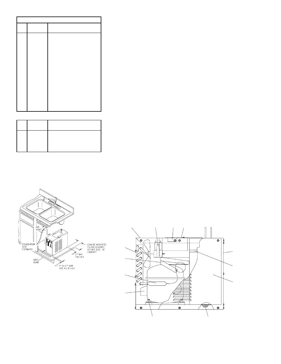
INSTALLATION
1. This unit is intended to be installed underneath a conventional kitchen sink, in a
cabinet not less than 36" (914mm) wide (inside dimension). Two air openings with a
minimum of 40" square (1016mm/square) each, minimum of 75% open area, must be
provided in the cabinet. One opening must be in the overhang of the toe space. The
other opening near the top of the cabinet. The remote unit must be installed with a
minimum of 3" clearance between the unit and the rear wall of the cabinet. It can be
installed flush against either side wall of the cabinet. The side louvers which are not
against the cabinet must not be blocked by objects located within 4" (102mm) of the
louvers. In addition, a minimum of 1 to 2" (25 to 51mm) clearance must be provided
between the toe space air opening and front of the unit.
2. Water inlet and outlet are 1/4" (6 mm) O.D. tubes with connectors supplied.
3. Connecting lines to be of copper, thoroughly flushed to remove all foreign matter
before being connected to cooler.
4. Connect cooler to building supply line with a shut-off valve and install a 3/8" O.D.
(10mm) unplated copper tube between the valve and cooler. Remove burr from
outside of water line. Insert water line into fitting until it reaches a positive stop,
approximately 3/4" (19mm).
5. Electrical: Make sure power supply is identical in voltage, cycle, and phase to that
specified on cooler serial plate. Never wire compressor directly to the power supply.
START-UP
1. Open supply line valve.
2. Purge air from all water lines by operating bubbler valve of fountain to which cooler
is connected. Steady stream assures all air is removed.
3. Rotate fan to insure proper clearance and free fan action.
4. Connect to electrical power.
TROUBLE SHOOTING & MAINTENANCE
Temperature Control: Factory set at 45°F (± 2°) under normal conditions. For colder
water, adjust screw on item no. 10 in clockwise direction.
Ventilation: Cabinet louvers and condenser fins should be periodically cleaned with
brush, air hose or vacuum cleaner. Excess dirt or poor ventilation can cause no cold
water and compressor cycling on the compressor overload protector.
Lubrication: Motors are lifetime lubricated.
Actuation of Quick Connect Water Fittings: Cooler is provided with lead-free
connectors which utilize an o-ring seal. To remove tubing from the fittings, relieve
water pressure, push in on gray collar while pulling on the tubing. To insert tubing,
push tube straight into fitting until it reaches a positive stop, approximately 3/4.
5
1, 8, 12, 13
10
3
4
19
2
18
14, 20, 21
16
17
15
6, 7, 9, 11