Remote operation, cont’d, Command/response table for sis commands (cont’d) – Extron electronic MVX 44 series User Manual
Page 56
Remote Operation, cont’d
MVX 44 / 48 / 84 / 88 VGA Matrix Switchers • Remote Operation
4-8
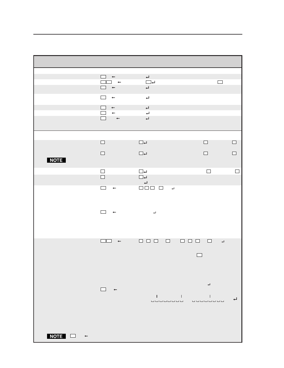
Command/response table for SIS commands (cont’d)
Command
ASCII Command Response
Additional description
(host to switcher)
(switcher to host)
Resets
Reset global presets
Esc
ZG
Zpg
Clear all global presets.
Reset individual global preset
Esc X10
ZG
Zpg
X10
Clear global preset
X10
.
Reset audio input levels
Esc
ZA
Zpa
Reset all input audio levels such
that the output is 0 dB.
Reset audio output levels
Esc
ZV
Zpv
Reset all output audio levels to the
professional level.
Reset all mutes
Esc
ZZ
Zpz
Unmute all outputs.
Reset all RGB delay settings
Esc
ZD
Zpd
Reset all RGB delays to 0 seconds.
Reset whole switcher
Esc
ZXXX
Zpx
Clear all ties and global presets,
and reset all audio gains to the
factory default.
View ties, gain, mutes, and presets
Read video
output tie
X3
&
X2
RGB input
X2
tied to output
X3
.
— or —
X3
%
X2
RGB input
X2
tied to output
X3
.
The & read RGB tie command and the % read RGB tie command can be used interchangeably
on the MVX switchers.
Read audio
output tie
X3
$
X2
Audio input
X2
tied to output
X3
.
Read
input gain
X1
G
X4
Example:
3G
-06
Audio input 3 level is -6 dB.
View all output mutes
Esc
VM
X7
1
X7
2
X7
3
...
X7
n
Mut
Each position listed in the
response is an output:
left = output 1, right = the
highest output number for this
model.
Example (MVX 84):
Esc
VM
0132Mut
Output 1 is unmuted, output 2
video is muted, output 3 video
and audio are muted, and output
4 audio is muted. Outputs 5
through 8 are not present on this
switcher.
View global preset
configuration
Esc X10
VC
X2
1
•
X2
2
•
X2
3
•...•
X2
n
•Vid•
X2
1
•
X2
2
•
X2
3
•...•
X2
n
•Aud
n is the highest output number
for this model switcher. Show
preset
X10
’s video and audio
configuration. Show the video
input tied to n sequential outputs
and then the audio input tied to
n sequential outputs.
Response description:
Video input # (I#) assigned to Output # (O#1)•I# assigned to O#2...I# assigned to O#8•Vid•
Audio I# assigned to O#1•I# assigned to O#2...I# assigned to O#8•Aud
Example (MVX 88):
Esc
4VC
1
Output:
Response = tied input:
Input 5 video tied to output 2
2 3 4 5 6 7 8
1 2 3 4
6•5•6•8•3•3•1•0•Vid•8•1•1•1•8•8•8•8•Aud
5 6 7 8
No tied input Audio input 8 tied to output 5
Each position shown in the response is an output: left = output 1, right = output 8. The number in each position is the
input tied to that output. Global preset 4 makes the following ties:
Video — Input 6 is tied to outputs 1 and 3; input 5 to output 2; input 8 to output 4; input 3 to outputs 5 and 6; and
input 1 to output 7. No input is tied to output 8.
Audio — Input 8 is tied to outputs 1 and outputs 5 through 8; input 1 to outputs 2 through 4.
Esc
0VC
commands the switcher to display the current configuration.