Echo 99944200610 User Manual
Page 8
8
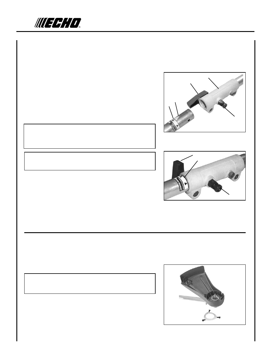
6. Rotate locator pin (A) 1/4 turn clockwise to engage lower shaft
hole. Insure locator pin is fully engaged by gently twisting
lower drive shaft. Locator pin (A) should snap flush in coupler.
Full engagement will prevent further shaft rotation.
7. Secure lower shaft assembly to coupler by tightening clamping
knob (D).
NOTE
Earlier model Power Heads may have shorter couplings. Short
couplings fit flush to decal point (E). New couplings are 4-3/4 in.
long, and fit flush to line (C).
NOTE
Lower bearing housing and head assembly must be in line with the
engine.
power
head
shafT
/
aTTaChmenT
lower
shafT
assembly
1. Set Power Head/Shaft Assembly on a level surface.
2. Pull locator pin (A) and rotate counter clockwise 1/4 turn to lock
out position.
3. Remove vinyl cap from attachment drive shaft.
4. Remove cardboard spacer, if necessary.
5. Carefully fit attachment lower drive shaft assembly into coupler (B)
to decal assembly line (C), making sure that the inner lower drive
shaft engages into the upper drive shaft mount.
plasTIC
shIeld
InsTallaTIon
(For Nylon Line Operation)
Parts Required: Plastic Shield, Shield Plate, three (3) 5mm x 16mm
screws.
NOTE
The plastic shield is for use with the Nylon Line Head only.
Install Metal Shield when using plastic or metal blades.
1. Place plastic shield on bottom of bearing housing flange.
2. Place shield plate on plastic shield, align holes. Install three (3)
screws from bottom through plate and shield into gear case.
A
B
D
E
C
D
C
A