Rs-232 connection - nexus meter to a computer, Nexus rs-485 wiring fundamentals, Nexus meter port 1 – Electro-Voice 1252 User Manual
Page 63
+ V - S B(-) A(+)
e
Electro Industries/GaugeTech
Doc # E107706 V1.25
5-5
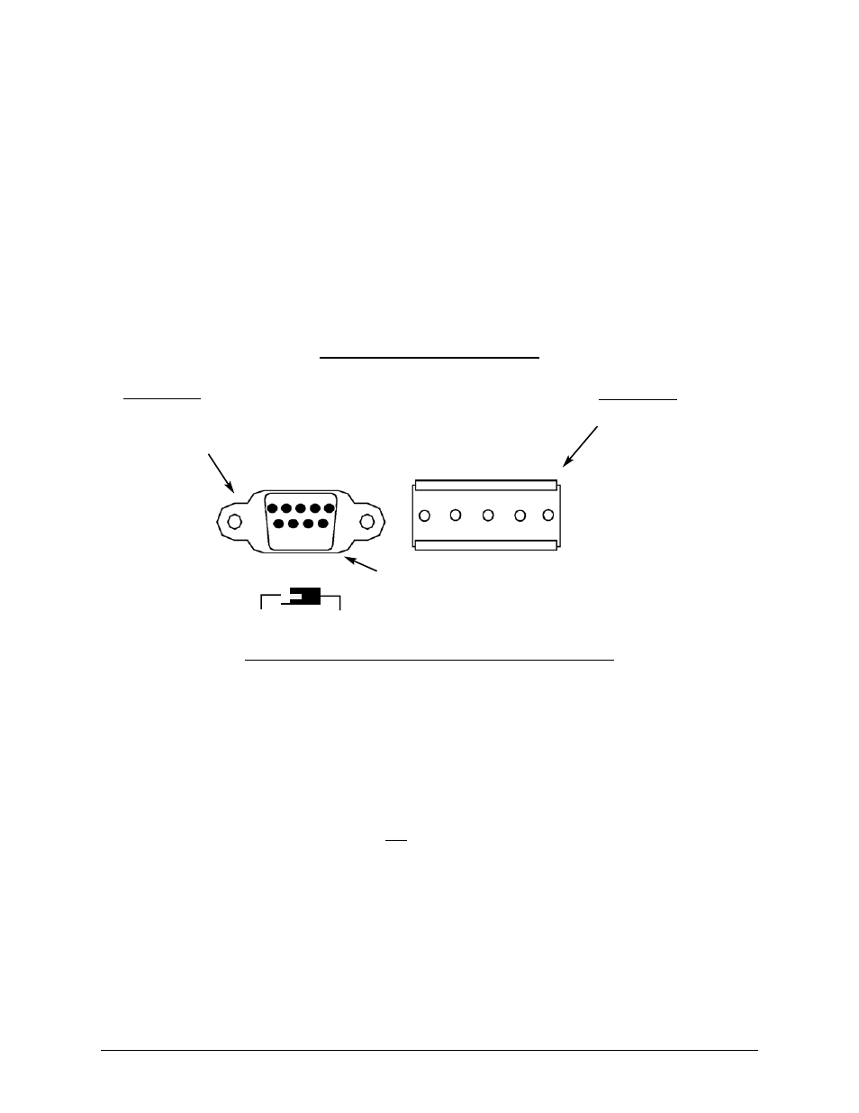
Figure 5.5: Nexus Port 1—RS-232/RS-485 Communication
Switch set for RS-232 communication
RS-232
RS-485
5 4 3 2 1
9 8 7 6
RS-232 Port
Pin #2=Transmit
Pin #3=Receive
Pin #5=Ground
RS-485 Port
(see Section 5.3 for details)
Nexus Meter Port 1
5.2: RS-2232 Connection—Nexus Meter to a Computer
Use Port 1 for RS-232 communication. Set the selector switch beneath the port to RS-232.
Insert one end of an RS-232 extension cable into the Nexus Meter’s 9-pin female serial port. Insert
the opposite end into a port on the computer.
The RS-232 standard limits the cable length to 50 feet (15.2m).
The RS-232 Port is configured as Data Communications Equipment (DCE).
5.3: Nexus RS-4485 Wiring Fundamentals (with RT Explanation)
Nexus RS-485 Ports (Ports 1–4)
(see Figure 5.5 above)
+V-
Voltage terminals for power connections: Use with Nexus I/O Modules and the
Nexus Displays only. The Nexus 1250/1252 Meter supplies 17V DC through the +V- ter-
minal connections. Note: Do not connect these pins to devices that receive power from
another source—ie, a computer—or to devices that do not require power to operate.
S
Shield: The Shield connection is used to reference the Nexus port to the same
potential as the source. It is not an earth-ground connection. You must also connect
the shield to earth-ground at one point. Do not connect the shield to ground at
multiple points; it will interfere with communication.
A(+)/B(-)
Two-wire, RS-485 communication terminals: Connect the A(+) terminal of the Nexus
Port to the (+) terminal of the device. Connect the B(-) terminal of the Nexus Port to the
(-) terminal of the device.