B 1 b1 s2, 0 specifications chart, b-series actuators, 0 configuration chart, b-series actuators – Enerpac Products UNI-LIFT M User Manual
Page 9
9
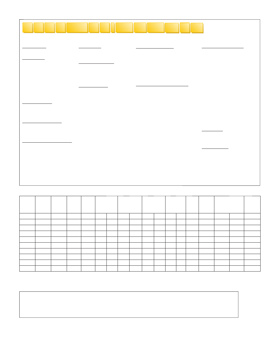
IMPORTANT:
• Product data, specifi cations and features are subject to change without notice.
• For system design guidelines and additional specifi cations, refer to the
Enerpac Uni-Lift
®
Catalog #E500.
B 1
B1
S2
M3
U R
L P
N
-
0240
A11
L63
1 Model Type
B = Ball Screw Actuator
2 Ton Rating
1 = 1 Ton
2 = 2 Ton
5 = 5 Ton
10 = 10 Ton
20 = 20 Ton
30 = 30 Ton
50 = 50 Ton
75 = 75 Ton
100 = 100 Ton
3 Mounting Style
U = Upright
I =
Inverted
D = Double Clevis *
4 Screw Configuration
T = Translating
R = Rotating
K = Keyed Translating
5
Extended Screw Length (ESL)
xxx.x = Input Valve (in.)
(Do not include decimal in
part No. - all data will be
based on 1 decimal place.)
Example: 12.0" = 0120"
6 Gear Ratio
L = Low
H = High
7 End Configuration
V = Threaded End
C = Clevis End
P = Plain End
T = Top Plate
8 Motor Adaptor
First Digit
A = Motor Adaptor
Second Digit
1 = Right-Hand Mount
2 = Left-Hand Mount
Third Digit
1 = 56C
2 = 143/145TC
3 = 182/184C
4 = 182/184TC
5 = 213/215C
6 = 213/215TC
9 Boot Specifications
First Digit
B = Boot
Second Digit
1 = 1 Boot, No Guides
2 = 2 Boots, No Guides
3 = 1 Boot, With Guides
4 = 2 Boots, With Guides
10 Limit Switch Configuration
First Digit
L = Limit Switch
Second Digit
1 = Right-Hand Position, 1
2 = Right-Hand Position, 2
3 = Right-Hand Position, 3
4 = Right-Hand Position, 4
5 = Left-Hand Position, 1
6 = Left-Hand Position, 2
7 = Left-Hand Position, 3
8 = Left-Hand Position, 4
Third Digit
1 = 2 Circuit Series 360
2 = 2 Circuit Series 1440
3 = 2 Circuit Series 4320
11 Motor Specifications
First Digit
M = Motor
Second & Third Digits
1 = 1/4 hp, 1750 RPM
2 = 1/4 hp, 1140 RPM
3 = 1/3 hp, 1750 RPM
4 = 1/3 hp, 1140 RPM
5 = 1/2 hp, 1750 RPM
6 = 1/2 hp, 1140 RPM
7 = 3/4 hp, 1750 RPM
8 = 3/4 hp, 1140 RPM
9 = 1 hp, 1750 RPM
10 = 1 hp, 1140 RPM
11 = 1.5 hp, 1750 RPM
12 = 1 hp, 1140 RPM
13 = 2 hp, 1750 RPM
14 = 2 hp, 1140 RPM
15 = 3 hp, 1750 RPM
12 Stop Nut
First Digit
N = Stop Nut
13 Single Shaft
First Digit
S = Shaft
Second Digit
1 = Right Hand
2 = Left Hand
* Double Clevis option is available only on models: B2, B5 and B10.
2
3
4
5
6
7
8
1
9
10
11
13
12
15.0 SPECIFICATIONS CHART, B-SERIES ACTUATORS
Capacity
Model
Number
Load
Screw
Diameter
Lead of
Screw
Gear
Center
Gear Ratio
(in)
Turns of input
shaft for 1 inch
of rise
Torque Required
to Lift 1 lbs.
(in-lbs)
Holding
Torque.
(ft-lbs)
No
Load
Torque
Maximum
Input
RPM
Estimated
Weight
(lbs)
Radius of
Gyration
(ton)
(in)
(in)
(in)
Low
High
Low
High
Low
High
Low
High
(in-lbs)
0" Travel
Per Inch
(in)
1
B1
.75
0.50
1.500
5:1
10:1
10
20
0.024
20
1.4
2
4
1800
2.3
0.7
0.154
2
B2
1.00
0.25
1.750
6:1
24:1
24
96
0.011
96
4
1.5
5
1800
17
0.6
0.205
5
B5
1.50
0.474
2.188
6:1
24:1
12.66
50.66
0.018
50.66
14
5
12
1800
35
0.6
0.285
10
B10
1.50
0.474
2.598
8:1
24:1
16.88
50.66
0.014
50.66
13
4
18
1800
50
0.8
0.285
20
B20
2.25
0.50
2.875
8:1
24:1
16
48
0.015
48
27
7
36
1800
85
1.5
0.463
30
B30
3.00
0.666
3.750
10
⅔:1
32:1
16
48
0.015
48
21
5
48
1200
220
2.4
0.620
50
B50
4.00
1.00
5.313
10
⅔:1
32:1
10.66
32
0.022
32
40
10
96
1200
340
2.8
0.835
75
B75
4.00
1.00
6.000
10
⅔:1
32:1
10.66
32
0.022
32
107
24
156
900
590
4.6
0.835
100
B100
4.00
1.00
7.500
12:1
36:1
12
36
0.020
36
128
50
204
900
960
4.6
0.835
14.0 CONFIGURATION CHART, B-SERIES ACTUATORS