M 1 b1 s2, 0 configuration chart, m-series actuators, 0 specifications chart, m-series actuators – Enerpac Products UNI-LIFT M User Manual
Page 8
8
M 1
B1
S2
M5
U T
L T
N
-
0240
A11
L62
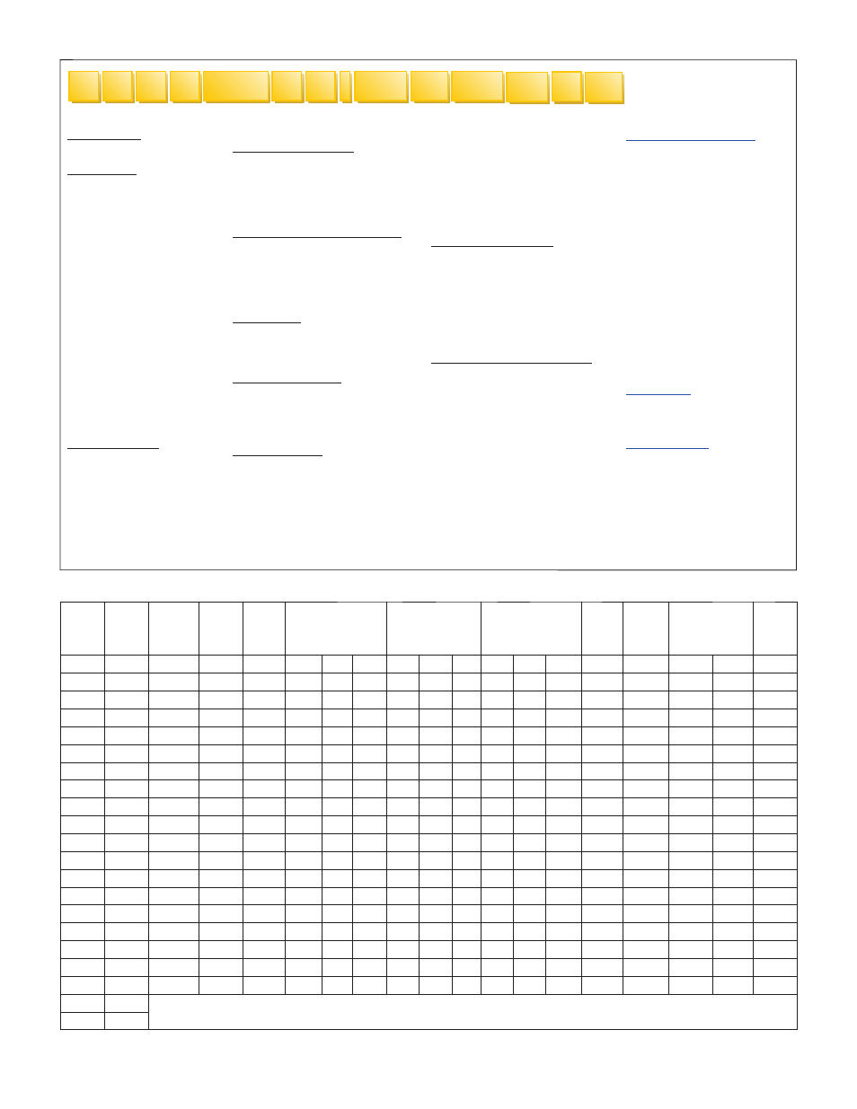
12.0 CONFIGURATION CHART, M-SERIES ACTUATORS
1 Model Type
M = Machine Screw Actuator
2 Ton Rating
A5 = .25 Ton
A15 = .75 Ton
A20 = 1 Ton
1 = 1 Ton
2 = 2 Ton
3 = 3 Ton
4 = 4 Ton
5 = 5 Ton
8 = 8 Ton
10 = 10 Ton
15 = 15 Ton
20 = 20 Ton
25 = 25 Ton
30 = 30 Ton
40 = 40 Ton
50 = 50 Ton
75 = 75 Ton
100 = 100 Ton
150 = 150 Ton
250 = 250 Ton
3 Mounting Style
U = Upright
I =
Inverted
D = Double Clevis *
2
3
4
5
6
7
8
1
4 Screw Configuration
T = Translating
R = Rotating
A =
Translating
(Anti-Backlash**)
K = Keyed Translating
5
Extended Screw Length (ESL)
xxx.x = Input Valve (in.)
(Do not include decimal in part
No. - all data will be based on 1
decimal place.
Example: 12.0" = 0120")
6 Gear Ratio
L = Low
M = Medium
H = High
7 End Configuration
V = Threaded End
C = Clevis End
P = Plain End
T = Top Plate
8 Motor Adaptor
First Digit
A = Motor Adaptor
Second Digit
1 = Right-Hand Mount
2 = Left-Hand Mount
Third Digit
1 = 56C
2 = 143/145TC
3 = 182/184C
4 = 182/184TC
5 = 213/215C
6 = 213/215TC
9 Booth Specifications
First Digit
B = Boot
Second Digit
1 = 1 Boot, No Guides
2 = 2 Boots, No Guides
3 = 1 Boot, With Guides
4 = 2 Boots, With Guides
10 Limit Switch Configuration
First Digit
L = Limit Switch
Second Digit
1 = Right Hand Position, 1
2 = Right Hand Position, 2
3 = Right Hand Position, 3
4 = Right Hand Position, 4
5 = Left Hand Position, 1
6 = Left Hand Position, 2
7 = Left Hand Position, 3
8 = Left Hand Position, 4
Third Digit
1 = 2 Circuit Series 360
2 = 2 Circuit Series 1440
3 = 2 Circuit Series 4320
11 Motor Specifications
First Digit
M = Motor
Second & Third Digits
1 = 1/4 hp, 1750 RPM
2 = 1/4 hp, 1140 RPM
3 = 1/3 hp, 1750 RPM
4 = 1/3 hp, 1140 RPM
5 = 1/2 hp, 1750 RPM
6 = 1/2 hp, 1140 RPM
7 = 3/4 hp, 1750 RPM
8 = 3/4 hp, 1140 RPM
9 = 1 hp, 1750 RPM
10 = 1 hp, 1140 RPM
11 = 1.5 hp, 1750 RPM
12 = 1 hp, 1140 RPM
13 = 2 hp, 1750 RPM
14 = 2 hp, 1140 RPM
15 = 3 hp, 1750 RPM
12 Stop Nut
First Digit
N = Stop Nut
13 Single Shaft
First Digit
S = Shaft
Second Digit
1 = Right Hand
2 = Left Hand
9
10
11
13
12
* Double Clevis option is available only on models: M2, M3, M4, M5, M10, M15 & M20.
**
Anti-Backlash option is available only on models: M2, M5, M10, M20, M30 & M50.
13.0 SPECIFICATIONS CHART, M-SERIES ACTUATORS
Capacity
Model
Number
Load
Screw
Diameter
Lead of
Screw
Gear
Center
Gear Ratio
(in)
Turns of input shaft
for 1 inch of rise
Torque Required
to Lift 1 lbs.
(in-lbs)
No Load
Torque
Maximum
Input
RPM
Estimated
Weight
(lbs)
Radius of
Gyration
(ton)
(in)
(in)
(in)
Low
Med.
High
Low
Med.
High
Low
Med.
High
(in-lbs)
0" Travel
Per Inch
(in)
.25
MA5
0.500
0.250
.0938
5:1
–
–
20
–
–
0.022
–
–
1.5
2587
2
0.1
0.094
.75
MA15
0.625
.25/.125
.0938
5:1
–
5:1
20
–
40
0.020
–
0.015
1.5/2.0
2587
2
0.1
0.125
1
MA20
0.75
0.20
1.250
5:1
–
20:1
25
–
100
0.020
–
0.010
4.0
2587
5
0.5
0.154
1
M1
0.75
0.25
1.500
5:1
–
10:1
20
–
40
0.021
–
0.013
3.0
2587
9
0.2
0.156
2
M2
1.00
0.25
1.750
6:1
–
24:1
24
–
96
0.020
–
0.009
5.0
1800
17
0.6
0.218
3
M3
1.00
0.25
1.831
6:1
8:1
12:1
24
8:1
48
0.021
0.017
0.013
4.0
1800
13
0.4
0.218
4
M4
1.50
0.33
2.256
5
⅓:1
12:1
24:1
16
12:1
72
0.030
0.018
0.012
5.0
1800
23
0.7
0.334
5
M5
1.50
0.38
2.188
6:1
–
24:1
16
–
64
0.028
–
0.011
12.0
1800
30
0.7
0.316
8
M8
1.75
0.33
3.010
6:1
–
12:1
18
–
36
0.030
–
0.019
7.0
1800
47
0.9
0.396
10
M10
2.00
0.50
2.598
8:1
–
24:1
16
–
48
0.029
–
0.015
18.0
1800
45
1.1
0.423
15
M15
2.25
0.50
2.598
8:1
–
24:1
16
–
48
0.031
–
0.015
18.0
1800
55
1.2
0.486
20
M20
2.50
0.50
2.875
8:1
–
24:1
16
–
48
0.033
–
0.021
36.0
1800
80
1.7
0.566
25
M25
2.75
0.50
4.005
9:1
–
18:1
18
–
36
0.031
–
0.019
10.0
1450
103
2.1
0.628
30
M30
3.38
0.67
3.750
10
⅔:1
–
32:1
16
–
48
0.034
–
0.017
48.0
1200
145
2.9
0.743
40
M40
4.25
0.67
5.162
–
–
20:1
–
–
30
–
–
0.024
12.0
1200
230
5.0
0.985
50
M50
4.25
0.67
5.313
10
⅔:1
–
32:1
16
–
48
0.040
–
0.021
96.0
1200
280
5.0
1.074
75
M75
5.00
0.67
6.003
10
⅔:1
–
32:1
16
–
48
0.042
–
0.021
156.0
900
495
6.3
1.149
100
M100
6.00
0.75
7.500
12:1
–
36:1
16
–
48
0.045
–
0.024
204.0
900
845
7.4
1.387
150
M150
Contact Enerpac
250
M250