Controls and installation, cont’d, On 1 2 3 4, P/2 da2 wm f/ec f rear panel – Extron Electronics P-2 DA2 WM F, WM F AAP, EC F, D User Manual
Page 8: P/2 da2 d rear panel, P/2 da2 wm f/ec f rear connectors, Figure 2-5 — p/2 da2 d rear connectors, Switch function on (up) off (down), Audio output — 3.5 mm captive screw stereo output, Above)
P/2 DA2 WM/EC/D/AAP Series • Controls and Installation
P/2 DA2 WM/EC/D/AAP Series • Controls and Installation
2-4
2-5
Controls and Installation, cont’d
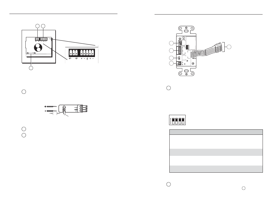
P/2 DA2 WM F/EC F rear panel
P/2 DA2 WM F/EC F rear connectors
N
Both WM F and WM EC F models have the same rear
panel connectors.
1
Power input —
12 - 24 VAC or DC (captive screw connector).
The center pole contains no conductor. Connect the conductors
to the outer two poles only.
2
Audio output —
3.5 mm captive screw stereo output
3
VGA output —
HD 15-pin female analog video output
connector
3
NC
12-24V AC/DC
R
L
NC
12-24V AC/DC
R
L
2
1
P/2 DA2 D rear panel
ON
1 2
3
4
1
2
3
4
5
12 V
0.2 A MAX
PO
WER
A
UDIO
OUTPUT
LR
CONFIG
VIDEO
OUTPUT
P/2 D
A2 D
ON
1 2
3
4
1 2
3
4
33
-166
3
-01 A 05 08
CONFIG Switches
SW 1
= Loc
a
l Monitor
ON=
Pre
sent, OFF= Not Pre
sent
SW 2
= A
u
dio O
u
p
u
t Config
ON=
S
tereo, OFF= D
ua
l MONO
SW
3
=
S
YNC Inp
u
t Imped
a
nce
ON= 510 Ohm,
OFF= 10 kOhm
SW 4
=
S
p
a
re
Extr
on Electr
onics
Anaheim, CA
VIDEO
GAIN
NORM
MED
HIGH
N15779
Figure 2-5 — P/2 DA2 D rear connectors
1
Configuration DIP switches —
The three DIP switches (plus
one spare) configure the P/2 DA2 D, as shown in the table
below.
N
The default DIP switch positions are set to On (up).
Set these switches before installing the distribution
amplifier in a wall.
ON 1 2 3 4
Switch Function On (up) Off (down)
SW1
SW2
SW3
SW4
local monitor
(set ID bits 4
and 11)
audio output
configuration
input sync
impedance
spare
monitor present
stereo
510 ohms
n/a
monitor not present
dual mono
10k ohms
n/a
2
Audio output —
3.5 mm captive screw stereo or dual mono
output (DIP switch selectable, see switch SW 2 in
1
above).
3-Pole Captive Screw Connector
Tie Wrap
3/16”
(5 mm) Max.