Controls and installation, Front and rear panels, Front faceplate – Extron Electronics P-2 DA2 WM F, WM F AAP, EC F, D User Manual
Page 7
P/2 DA2 WM/EC/D/AAP Series • Controls and Installation
P/2 DA2 WM/EC/D/AAP Series • Controls and Installation
Unity –
output signal level is same as that of input with no added
peaking
50% –
increases the output signal level and adds 50% of the maximum
peaking to the signal
N
If the edges of the image seem to exceed their boundaries,
or if thin lines and sharp edges look thick and fuzzy, try
changing the level/peak setting.
P/2 DA2 WM EC F faceplate features
P/2 DA2 D faceplate features
2-3
Controls and Installation
Front and Rear Panels
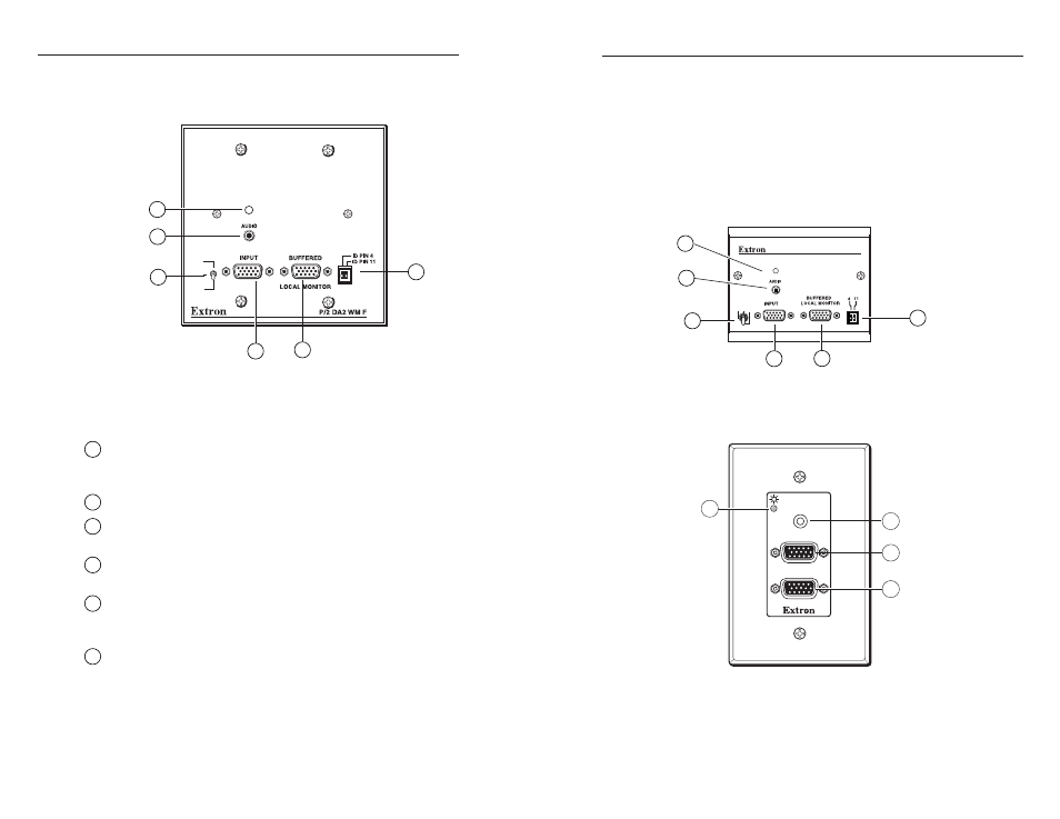
Front faceplate
P/2 DA2 WM F faceplate features
N
Both WM F and WM EC F models have the same front
and rear panel connectors and features.
1
2-color power/signal LED —
lights amber to indicate power on
only; lights green to indicate power on with video signal
present.
2
Audio input jack —
3.5 mm stereo input
3
VGA input connector —
HD 15-pin female analog video input
connector
4
Buffered local monitor output
— HD 15-pin female for output
to a local monitor
5
ID bit termination DIP switches
— provides proper ID bit
termination for a laptop computer that is not attached to a local
monitor. See “Setting the DIP switches” in this chapter.
6
3-position gain/peaking switch
— compensates for cable
capacitance and resistance due to long cable runs; position
switch for best image on the output display device.
100% –
increases the output signal level and adds 100% of the
maximum peaking to the signal
2-2
AUTO POWER
P/2 DA2 WM F EC
ID PINS
100%
UNITY
50%
GAIN/
PEAKING
2
6
3
4
5
1
AUDIO IN
COMPUTER IN
MONITOR OUT
1
2
3
4
AUTO POWER
100%
UNITY
50%
GAIN/PEAKING
1
2
3
4
5
6