Table 6: physical data, Table 7: dhg voltage limitations, Table 8: minimum clearances – Energy Tech Laboratories DHG240 User Manual
Page 13: Table 9: dhg electrical data
035-17233-000-C-0702
Unitary Products
13
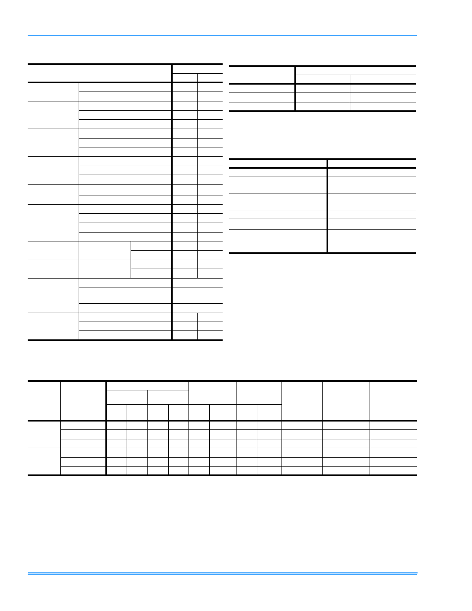
TABLE 6: PHYSICAL DATA
MODELS
DHG
180
240
EVAPORATOR
BLOWER
Centrifugal Blower (Dia. x Wd. in.)
15 x 15
18 x 15
Fan Motor HP
5
7.5
EVAPORATOR
COIL
Rows Deep
4
4
Fins Per Inch
13.5
13.5
Face Area (Sq. Ft.
15.5
20.0
CONDENSER
FANS
(Two Per Unit)
Propeller Dia. (in.) (Each)
30
30
Fan Motor Hp (Each)
1
1
Nom. CFM (Each)
5765
7000
CONDENSER
COILS
(Two Per Unit)
Rows Deep (Each)
3
3
Fins Per Inch (Each)
13
15
Face Area (Sq. Ft.) (Total)
36.0
43.3
COMPRESSOR
(Qty. Per Unit)
10-Ton Tandem Hermetic Recip.
1
1
2
5-Ton Hermetic Recip.
1
-
AIR
FILTERS
Quantity Per Unit (16” X 20” X 2”)
-
4
Quantity Per Unit (16” X 25” X 2”)
-
4
Quantity Per Unit (18” X 24” X 2”)
5
-
Total Face Area (sq. ft.)
15.0
20.0
CHARGE
Refrigerant 22
(lbs./oz.)
System #1
29/9
23
System #2
14/8
23/12
BASIC
UNIT
DHG
(Gas/Electric)
240Mbh (lbs)
2100
2300
320Mbh (lbs)
2140
2340
OPTIONS
Economizer (lbs)
160
Economizer with
Power Exhaust (lbs)
245
Motorized Damper (lbs)
150
ACCY.
Roof Curb (lbs)
175
185
Barometric Damper (lbs)
45
45
Wood Skid (lbs)
220
220
1
This compressor will be energized first.
TABLE 7: DHG VOLTAGE LIMITATIONS
1
POWER SUPPLY
VOLTAGE
MIN.
MAX.
208/230-3-60
187
253
460-3-60
414
506
575-3-60
518
506
1
Utilization Range “A” in accordance with ARI Standard
110.
TABLE 8: MINIMUM CLEARANCES
LOCATION
CLEARANCE
Front
36”
Back
24” (Less Economizer)
49” (With Economizer
Left Side (Filter Access)
24” (Less Economizer)
36” (With Economizer)
Right Side (Cond. Coil)
36”
Below Unit
1
1
Units may be installed on combustible floors made
from wood or class A, B, or C roof covering material.
0”
Above Unit
2
2
Units must be installed outdoors. Overhanging struc-
tures or shrubs should not obstruct condenser air dis-
charge outlet.
72” With 36” Maximum
Horizontal Overhang (For
Condenser Air Discharge)
TABLE 9: DHG ELECTRICAL DATA
MODEL
POWER
SUPPLY
COMPRESSORS
COND. FAN
MOTORS
(#1 & #2)
SUPPLY AIR
BLOWER
MOTOR
MIN.
CIRCUIT
AMPACITY
(AMPS)
MAX. TIME
DELAY FUSE
SIZE (AMPS)
MIN.
1
WIRE
SIZE 75°C
#1
#2
RLA
LRA
RLA
LRA
HP
(ea.)
FLA
(ea.)
HP
FLA
DHG180
208/230-3-60
28.6
274
14.3
137
1
4.1/4.2
5
11.8
77.8/77.0
90
4
460-3-60
14.4
138
7.2
69
1
2.1
5
5.9
42.7
50
8
575-3-60
11.4
116
5.7
58
1
1.4
5
5.2
30.7
35
8
DHG240
208/230-3-60
28.6
274
28.6
274
1
4.1/4.2
7.5
18.6
98.6/96.8
110
3
460-3-60
14.4
138
14.4
138
1
2.1
7.5
9.3
52.2
60
6
575-3-60
11.4
116
11.4
116
1
1.4
7.5
7.5
40.2
45
8
1
Although these sizes are based on copper conductors aluminum wire can be used. Refer to the national electric code (in USA) or
the current Canadian Electrical Code (in Canada) to determine the proper size.