Warning, Correct, Single speed leg assembly procedure – SAF-HOLLAND XL-LG315-01 Formula 150 Landing Gear (Manufactured after March 1, 2000) User Manual
Page 3: Gearbox leg assembly procedure, Alignment, See page 4 for exploded view and parts list
SINGLE SPEED LEG ASSEMBLY
PROCEDURE
(continued)
:
7.
Put key (9) into slot on shaft (11). Slide gear (10) over
key (9) on shaft (11). Check for free movement by
rotating shaft (11) (minimum end play 1/32"). It may
be necessary to add or remove shims.
8.
Fill with permanent type grease (1 pound capacity).
9.
Install gasket (7), cover (6) and screws (5). Check to
see that the gears turn freely.
10. Install landing gear on trailer. Adjust both legs to
the same extended length and install cross shaft (36),
bolts (20) and nuts (19). Cross shaft must have
enough end play and must rotate freely–adjust bolts
accordingly. Mounting bolts should be torqued to 100
ft-lbs minimum.
GEARBOX LEG ASSEMBLY PROCEDURE:
1.
Replace all worn and broken parts.
2.
Install bushings (34) or (35) if removed.
3.
Follow steps 3 through 5 in "Single Speed Assembly
Procedure," above.
4.
Install gear (33) on shaft (32).Put key (9) into slot on
shaft (32) and slide gear (33).
5.
Insert shaft (32) through top hole in gearbox. Slide
washer (12) onto shaft inside upper leg (3). Position
gear (10) on top of gear (13), making certain gear is
oriented as shown in the exploded view, with hole
facing up. Check for free movement (minimum 1/32"
end play).
6.
Fill with 1 pound of permanent type grease.
Install gasket (7), cover (6), and screws (5).
7.
Insert pin (31) in shaft (27). Slide gear (28) on shaft
(27) until pin engages in slot on gear (28). Then insert
pin (30) in front of gear (28).
8.
Install shifter spring (29) and locate with screw (5)
installed loosely into gearbox.
9.
Insert shaft (27) through shifter spring (29) and lower
hole of gearbox. Tighten screw (5). Slide shaft (27) in
until spring seats in either groove in shaft (27) and
has full tooth engagement with gear (33).
10. Lubricate gears with 1 pound of permanent type
grease. Install gasket (26), cover (25), bolts (24) and
nuts (23). Tighten to 10 ft-lbs torque.
11. For installation, refer to step 11 in "Single Speed Leg
Assembly Procedure."
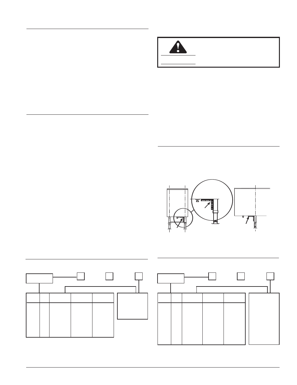
ALIGNMENT:
Using a square, check that both landing gear legs are
square with the trailer and parallel with each other as
shown. Bent or damaged legs are an indication of possible
damage to the lift screw, lift nut or other internal compo-
nents and should be replaced.
SQUARE
SQUARE
TRAILER
END
VIEW
SQUARE
CORRECT
TRAILER
END
VIEW
WARNING
Pin (30) must not extend more
than 1/8" above the shaft surface.
CHART 2: Inner Leg and Outer Leg
CHART 1: Shaft Requirements
TRAVEL
MTG
ITEM (11)
ITEM (32)
ITEM (27)
CODE
CODE
PART NO.
PART NO.
PART NO.
1
A
LG2127
LG2099
XA-06226-A
1
B
LG2127-10
LG2099-10
XA-06226-B
1
C
LG2127-20
LG2099-20
XA-06226-C
1
D
LG2127-30
LG2099-30
XA-06226-C
2
A
LG2127
LG2099
XA-06226-A
2
B
LG2127-10
LG2099-10
XA-06226-B
2
C
LG2127-20
LG2099-20
XA-06226-C
2
D
LG2127-30
LG2099-30
XA-06226-C
TRAVEL
CODE
MOUNTING
CODE
FOOTWARE
CODE
1 – 17˝ TRAVEL
2 - 19˝ TRAVEL
This product is covered by Holland’s Formula 150 5-year parts and 2-year labor warranty. Holland reserves the right,
without giving prior notice, to change specifications and dimensions as designs are altered or improved.
A – UNIVERSAL
B – INSIDE
C – OUTSIDE
D – OUTSIDE,
EXTRA
LONG
TRAVEL
FTWR
ITEM (1)
ITEM (2)
ITEM (3)
CODE
CODE*
PART NO.
PART NO.
PART NO.
1
T
LG2135-01
LG2093-02
LG2136-02
1
U
LG2129-01
LG2093-01
LG2136-01
1
V
LG2129-01
LG2093-01
LG2136-01
1
X
LG2129-01
LG2093-01
LG2136-01
1
Y
LG2129-01
LG2093-01
LG2136-01
2
T
LG2135-02
LG2093-03
LG2136-03
2
U
LG2129-02
LG2093-02
LG2136-02
2
V
LG2129-02
LG2093-02
LG2136-02
2
X
LG2129-02
LG2093-02
LG2136-02
2
Y
LG2129-02
LG2093-02
LG2136-02
TRAVEL
CODE
FOOTWARE
CODE
MOUNTING
CODE
1 – 17˝ TRAVEL
2 - 19˝ TRAVEL
T 10˝ Diameter
Shockfoot
U Heavy Duty Skid
Foot, 10x10x4
1
/
2
V Low Profile Skid
Foot, 10x10x2
X No Footware
Y Skid Foot
10x10x4
1
/
2
* FOOTWARE
CODE
LEGEND
See page 4 for Exploded View and Parts List
3