Power supply timing relationships and diagram – Purdy AND1742MST2 User Manual
Page 3
Intelligent Graphics Display
AND1742MST2
Purdy Electronics Corporation • 720 Palomar Avenue • Sunnyvale, CA 94085
3
Tel: 408.523.8200 • Fax: 408.733.1287 • [email protected] • www.purdyelectronics.com
3/21/07
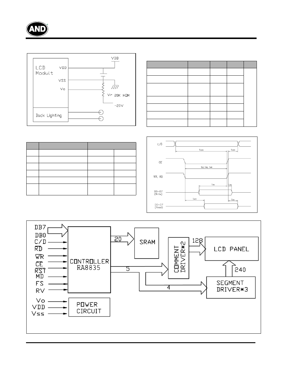
Power Supply
Timing Relationships and Diagram
Timing Diagram
Block Diagram
Signal Timing Relationships
Item
Symbol
Min.
Max.
Unit
C/D Set Up Time
t
CDS
100
–
ns
C/D Hold Time
t
CDH
10
–
CE
,
RD
,
WR
Pulse Width
t
CDS
, t
CDS
,
t
CDS
80
–
Data Set Up Time
t
DS
80
–
Data Hold Time
t
DH
40
–
Access Time
t
ACC
–
150
Output Hold Time
t
OH
10
50
Reliability Test
No.
Item
Conditions
1
High Temp. Operation
70ºC
120 HR
2
High Temp. Storage
80ºC
120 HR
3
Low Temp. Operation
-20ºC
120 HR
4
Low Temp. Storage
-30ºC
120 HR
5
High Temp./Humid Storage
60ºC 90%RH
120 HR
6
Thermal Shock
-20ºC, 30 min.
+60ºC, 30 min.
10 cycle
Controller: RA8835
- AND671GST-LED (4 pages)
- AND471GST (2 pages)
- AND671WGST-LED (6 pages)
- AND471GST-LED (4 pages)
- AND481GST-LED (2 pages)
- AND491GST (2 pages)
- AND491GST-LED (2 pages)
- AND731GST/GST-LED (2 pages)
- AND491GST3-3V-W-LED (4 pages)
- AND721GST/GST-LED (2 pages)
- AND501WGST/WGST-LED (2 pages)
- AND501GST/GST-LED (2 pages)
- AND791GST/GST-LED (3 pages)
- AND591GST/GST-LED (2 pages)
- AND081GST/GST-LED (3 pages)
- AND082GST/GST-LED (3 pages)
- ANDpSi056ET0S-HB-KIT (3 pages)
- AND-TFT-64PA-KIT (6 pages)
- PC-TFT-20TD (8 pages)
- AND-TFT-56LP (6 pages)
- AND-TFT-8LP (6 pages)
- ANDpSio8C351-HB-KIT (5 pages)
- AND064VT8-HB-LED (11 pages)
- AND-TFT-7LP (6 pages)
- ANDpSi089C362S-KIT (10 pages)
- PC-TFT-25XS (11 pages)
- ANDpSi121GAOS-HB-KIT (5 pages)
- AND12C285-DHB-KIT (5 pages)
- AND-TFT-35XS-LED-KIT (8 pages)
- AND-TFT-43LP (5 pages)
- AND-TFT-5VX-KIT (11 pages)
- AND-TFT-35VX-KIT (13 pages)
- FE1901 (1 page)
- FE0502 (1 page)
- AND-TFT-5VX-4HB-KIT (12 pages)
- AND050VL-LED-KIT (12 pages)
- AND1781STN-LED (4 pages)
- AND1743BST-LED (6 pages)
- AND1781MST-LED (4 pages)
- AND1743MST-LED (4 pages)
- AND3222MST2 (4 pages)
- AND3222MST-LEDW (5 pages)
- AND1743FST-LED (4 pages)
- AND1391ST-EO (4 pages)