And-tft-25xs-led-kit – Purdy AND-TFT-25XS-LED-KIT User Manual
Page 9
Purdy Electronics Corporation • 720 Palomar Avenue • Sunnyvale, CA 94085
6/27/08
Tel: 408.523.8200 • Fax: 408.733.1287 • [email protected] • www.purdyelectronics.com
9
Terminal Pin Assignment
Pin No.
Symbol
I/O
Description
1
STH
I/O
Start pulse for source driver
2
AV
SS
I
Analog GND for source driver
3
AV
DD
I
Analog power input for source driver
4
V
B
I
Video Input B
5
V
G
I
Video Input G
6
V
R
I
Video Input R
7
V
SS
I
Digital GND
8
V
DD
I
Digital power input
9
CPH1
I
Sampling and shift clock for source driver
10
CPH2
I
Sampling and shift clock for source driver
11
CPH3
I
Sampling and shift clock for source driver
12
STH2
I/O
Start pulse for source driver
13
Q2H
I
Video input rotation control
14
INH
I
Output enable for source driver
15
R/L
I
Left/Right Control for source driver
16
V
COM
I
Common electrode voltage
17
XOE
I
Output enable for gate driver
18
CPV
I
Clock input for gate driver
19
U/D
I
Up/Down Control for gate driver
20
DIO2
I/O
Vertical start pulse
21
DIO1
I/O
Vertical start pulse
22
V
GL
I
Gate off voltage (alternative every 1-H)
23
V
EE
I
Gate driver negative voltage
24
V
SS
I
GND
25
V
CC
I
Logic power for gate driver
26
V
GH
I
Gate on voltage
27
NC
–
No connection
28
NC
–
No connection
29
GLED
Supply current for LED
30
VLED
Supply voltage for LED
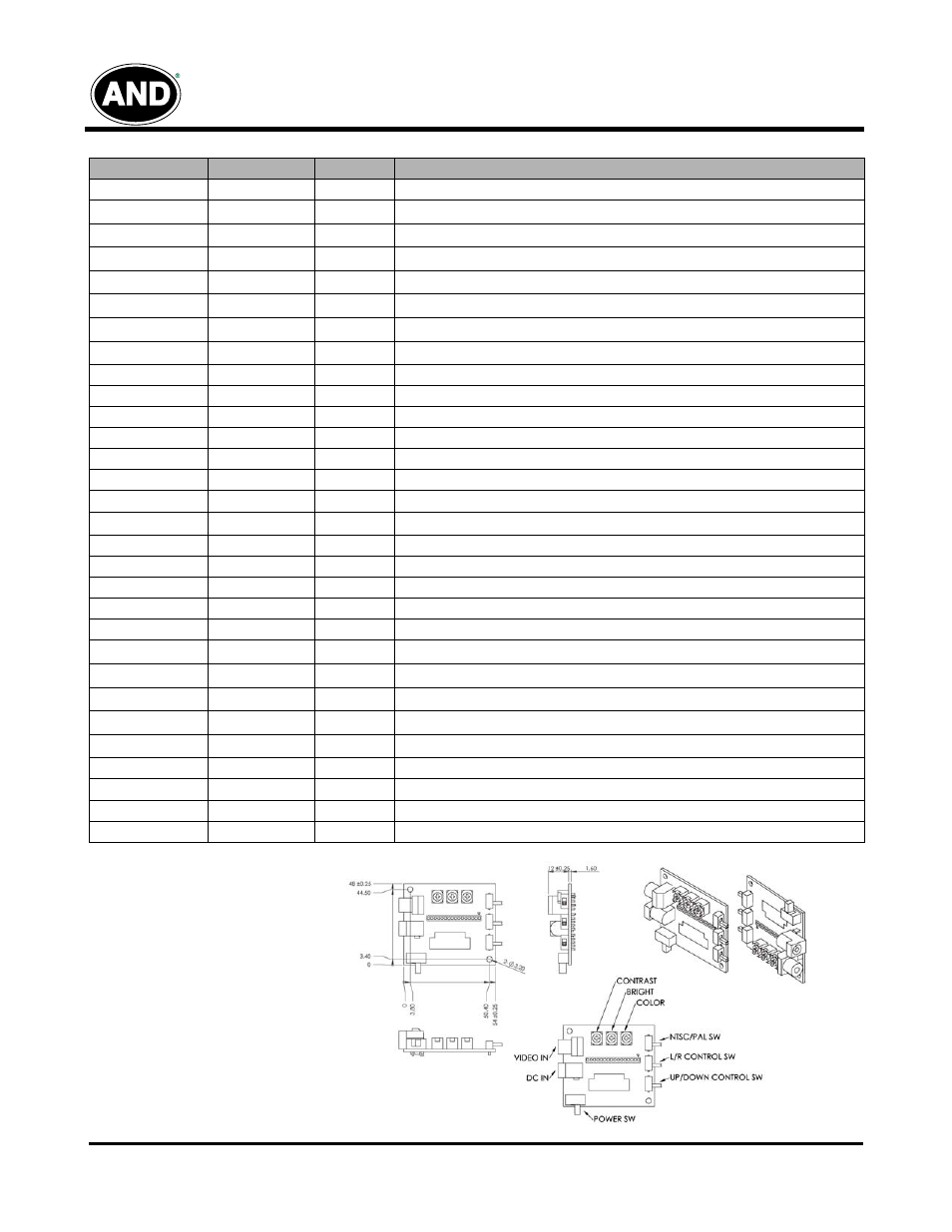
AND-TFT-25XS-LED-KIT
2535 Demo Board