And-tft-25xs-led-kit – Purdy AND-TFT-25XS-LED-KIT User Manual
Page 10
Purdy Electronics Corporation • 720 Palomar Avenue • Sunnyvale, CA 94085
10
Tel: 408.523.8200 • Fax: 408.733.1287 • [email protected] • www.purdyelectronics.com
6/27/08
J301: Pin Assignment of SIgnal Input (Pitch 1.25 mm 15P, Side Entry Type)
Pin No.
Symbol
I/O
Description
Remarks
1
Vin
I
+12 V Voltage Power supply
2
GND
–
Power Ground
3
GND
–
Power Ground
4
GND
–
Signal Ground
5
Video-IN
I
Video input (1Vp-p/75
Ω)
6
+5V
O
Voltage DC Output
Note 1
7
Bright
I
Brightness control
8
Contrast
I
Contrast control
9
Color
I
Color control
10
Tint
I
Tint control
Note 2
11
NTSC/PAL
O
Systemm Auto detect output
Note 3
12
LRC
I
Screen Left / Right reverse
Note 4
13
UDC
I
Screen Up / Down reverse
Note 4
14
Dimmer
I
Backlight brightness control
15
Enable
I
Backlight On/Off
Note 5
Note 1: The +5V power supply external control circuit. (Max. output is 10mA)
Note 2: The TINT is only operating in NTSC system.
Note 3: The output High level for NTSC mode and Low level for PAL mode.
Note 4: Default +5V or floating is normal scanning and 0V is for reversed scanning.
Note 5: The floating or 0V is backlight on and 5V is backlight off.
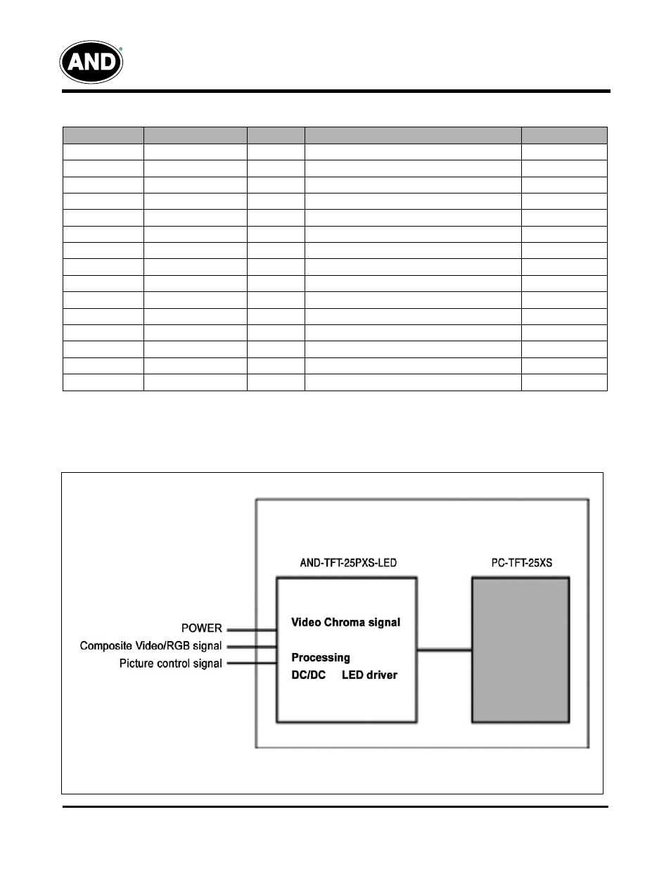
Block DIagram
AND-TFT-25XS-LED-KIT