Notice – Thermo Pride DryR22 (LX-13) User Manual
Page 3
3
LIQUID LINE FILTER-DRIER
The air conditioning unit’s copper spun filter/dryer is located on the liq-
uid line.
PIPING CONNECTIONS
The outdoor condensing unit must be connected to the indoor evapora-
tor coil using field supplied refrigerant grade (ACR) copper tubing that is
internally clean and dry. Units should be installed only with the tubing
sizes for approved system combinations as specified in tabular data
sheet. The charge given is applicable for total tubing lengths up to 15
feet. See Application Data Part Number 247077 for installing tubing of
longer lengths and elevation differences.
PRECAUTIONS DURING LINE INSTALLATION
1.
Install the lines with as few bends as possible. Care must be taken
not to damage the couplings or kink the tubing. Use clean hard
drawn copper tubing where no appreciable amount of bending
around obstruction is necessary. If soft copper must be used, care
must be taken to avoid sharp bends which may cause a restriction.
2.
The lines should be installed so that they will not obstruct service
access to the coil, air handling system, or filter.
3.
Care must also be taken to isolate the refrigerant lines to minimize
noise transmission from the equipment to the structure.
4.
The vapor line must be insulated with a minimum of 1/2" foam rub-
ber insulation (Armaflex or equivalent). Liquid lines that will be
exposed to direct sunlight, high temperatures, or excessive humid-
ity must also be insulated.
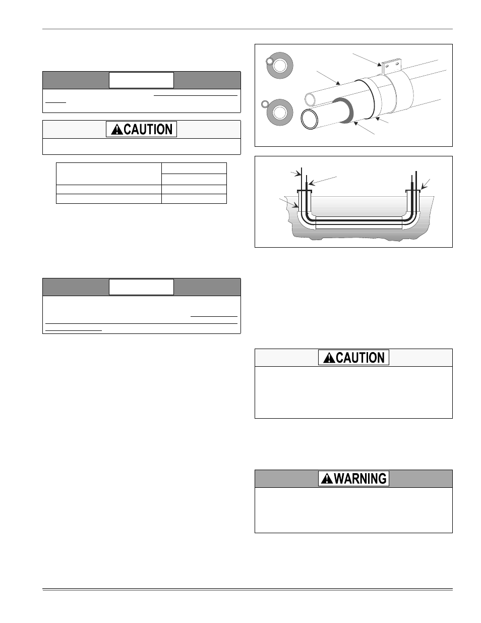
5.
Tape and suspend the refrigerant lines as shown. DO NOT allow
tube metal-to-metal contact. See Figure 2.
6.
Use PVC piping as a conduit for all underground installations as
shown in Figure 3. Buried lines should be kept as short as possible
to minimize the build up of liquid refrigerant in the vapor line during
long periods of shutdown
7.
Pack fiberglass insulation and a sealing material such as perma-
gum around refrigerant lines where they penetrate a wall to reduce
vibration and to retain some flexibility.
8.
For systems with total line length exceeding 50 feet, see APPLI-
CATION DATA and worksheet "General Piping Recommendations
and Refrigerant Line Length" for vapor and liquid line sizing, cali-
bration of liquid line pressure loss or gain, determination of vapor
line velocity, elevation limitations, orifice connections, system
charging, traps, etc.
PRECAUTIONS DURING BRAZING OF LINES
All outdoor unit and evaporator coil connections are copper-to-copper
and should be brazed with a phosphorous-copper alloy material such
as Silfos-5 or equivalent. DO NOT use soft solder. The outdoor units
have reusable service valves on both the liquid and vapor connections.
Units are shipped from factory with a nitrogen holding charge. Refer to
Tabular Data Sheet for refrigerant charge quantities. Reusable service
valves are provided to evacuate and charge per this instruction.
Serious service problems can be avoided by taking adequate precau-
tions to assure an internally clean and dry system.
PRECAUTIONS DURING BRAZING SERVICE VALVE
Precautions should be taken to prevent heat damage to service valve
by wrapping a wet rag around it as shown in Figure 4. Also, protect all
painted surfaces, insulation, and plastic base during brazing. After braz-
ing, cool joint with wet rag.
Valve can be opened by removing the plunger cap and fully inserting a
hex wrench into the stem and backing out counter-clockwise until valve
stem just touches the chamfered retaining wall.
Replacements for the liquid line drier must be exactly the same as
marked on the original factory drier. See Source 1 for O.E.M. replace-
ment driers.
Failure to do so or using a substitute drier or a granular type may
result in damage to the equipment.
Filter-Drier
Source 1 Part No.
Apply with Models
13 SEER
S1-02922156000
1.5 to 3 Tons
S1-02922157000
3.5 to 5 Tons
Using a larger than specified line size could result in oil return prob-
lems. Using too small a line will result in loss of capacity and other
problems caused by insufficient refrigerant flow. Slope horizontal
vapor lines at least 1" every 20 feet toward the outdoor unit to facili-
tate proper oil return.
NOTICE
NOTICE
FIGURE 2: Installation of Vapor Line
FIGURE 3: Underground Installation
Dry nitrogen should always be supplied through the tubing while it is
being brazed, because the temperature required is high enough to
cause oxidation of the copper unless an inert atmosphere is provided.
The flow of dry nitrogen should continue until the joint has cooled.
Always use a pressure regulator and safety valve to insure that only
low pressure dry nitrogen is introduced into the tubing. Only a small
flow is necessary to displace air and prevent oxidation.
This is not a backseating valve. The service access port has a valve
core. Opening or closing valve does not close service access port.
If the valve stem is backed out past the chamfered retaining wall, the
O-ring can be damaged causing leakage or system pressure could
force the valve stem out of the valve body possibly causing personal
injury.
Liquid
Line
Incorrect
Correct
Tape
Sheet Metal Hanger
Insulated Vapor Line
TO INDOOR COIL
Liquid Line
PVC
Conduit
Insulated
Vapor Line
TO OUTDOOR UNIT
Cap