Installation, Product installation – Rose Electronics CrystalView DVI Multi User Manual
Page 8
INSTALLATION
4
CrystalView DVI Multi Installation and Operations Manual
Product Installation
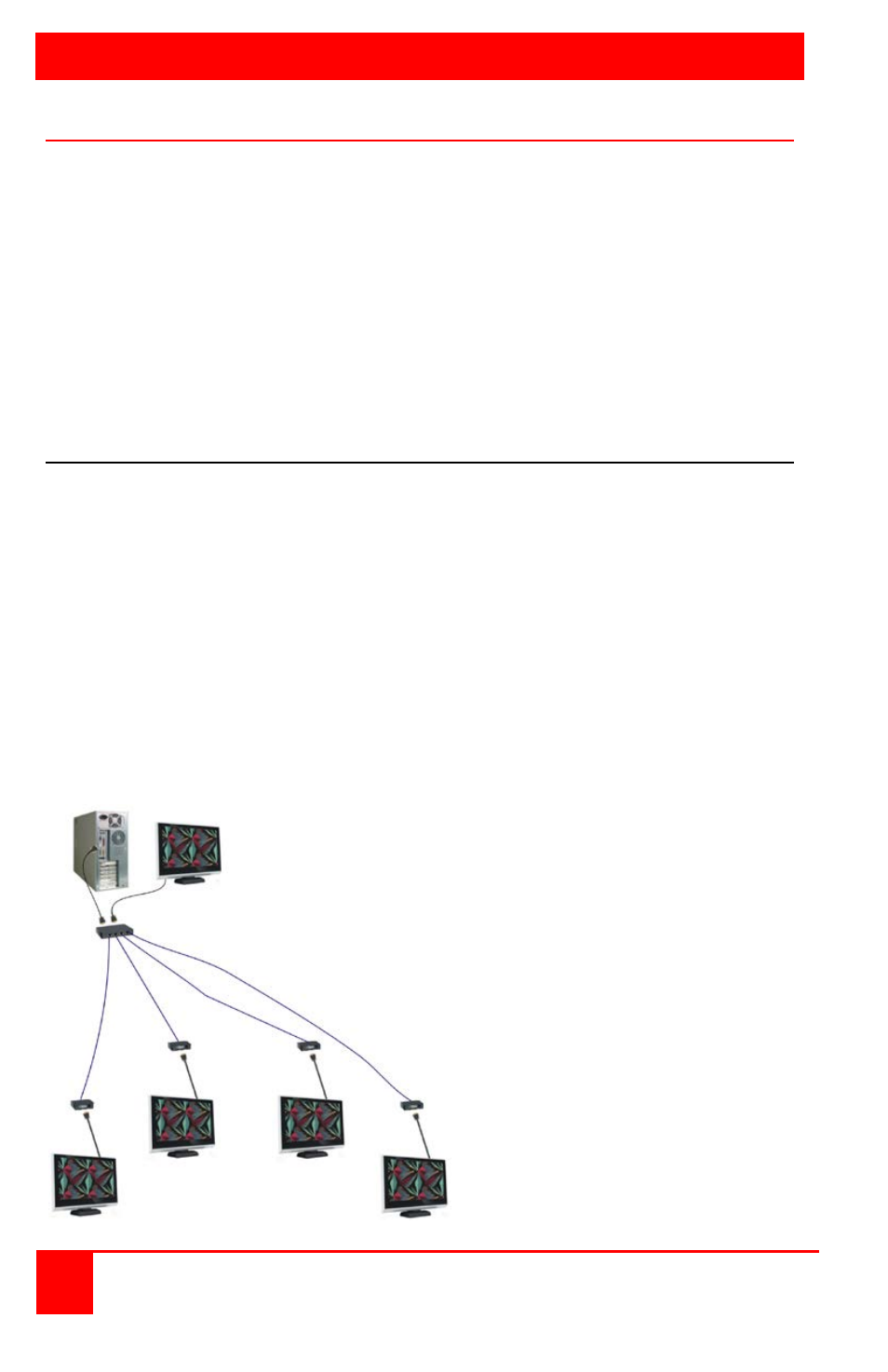
Figure 1 shows a typical installation of the CrystalView DVI Multi using the
x2 model. All models install in the same manor. The x1 model uses 1
CAT6 cable from the transmitter to one receiver; the x2 model uses 2
CAT6 cables from the transmitter to two receivers; the x4 model uses 4
CAT6 cables from the transmitter to four receivers; the x8 model uses 8
CAT6 cables from the transmitter to eight receivers. Each CAT6 cable can
be up to 220 feet in length. It is recommended that all monitors connected
to the receiver unit(s) (1, 2, 4, or 8) be the same make, model, and type of
monitor.
EDID Learning procedure
The CrystalView DVI Multi has its own built-in EDID table and uses these
monitor specifications in place of the actual monitor’s EDID specifications.
The Transmitter unit can “Learn” the monitor’s EDID specifications and
provide these to the computer so the correct resolutions and refresh rates
can be used.
To set-up the Transmitter to “Learn” the monitor’s EDID specifications,
connect the DVI monitor to the DVI-OUT connector on the transmitter and
apply power to the Transmitter. On power-up the CrystalView DVI Multi
will read and store the EDID specifications of any monitor connected to the
DVI-OUT connector.
If no monitor is connected to the DVI OUT connector during power-up, the
internal EDID information is not modified.