MEDC Ex ResistTel IP2 User Manual
Page 15
Manual ExResistTel
IP2
Page 15
The diameter of the drilled hole is dependent on the screw employed (screw
diameter max. 8 mm) and the type of supporting base material (steel, wood,
concrete, plasterboard etc.) and must be chosen accordingly.
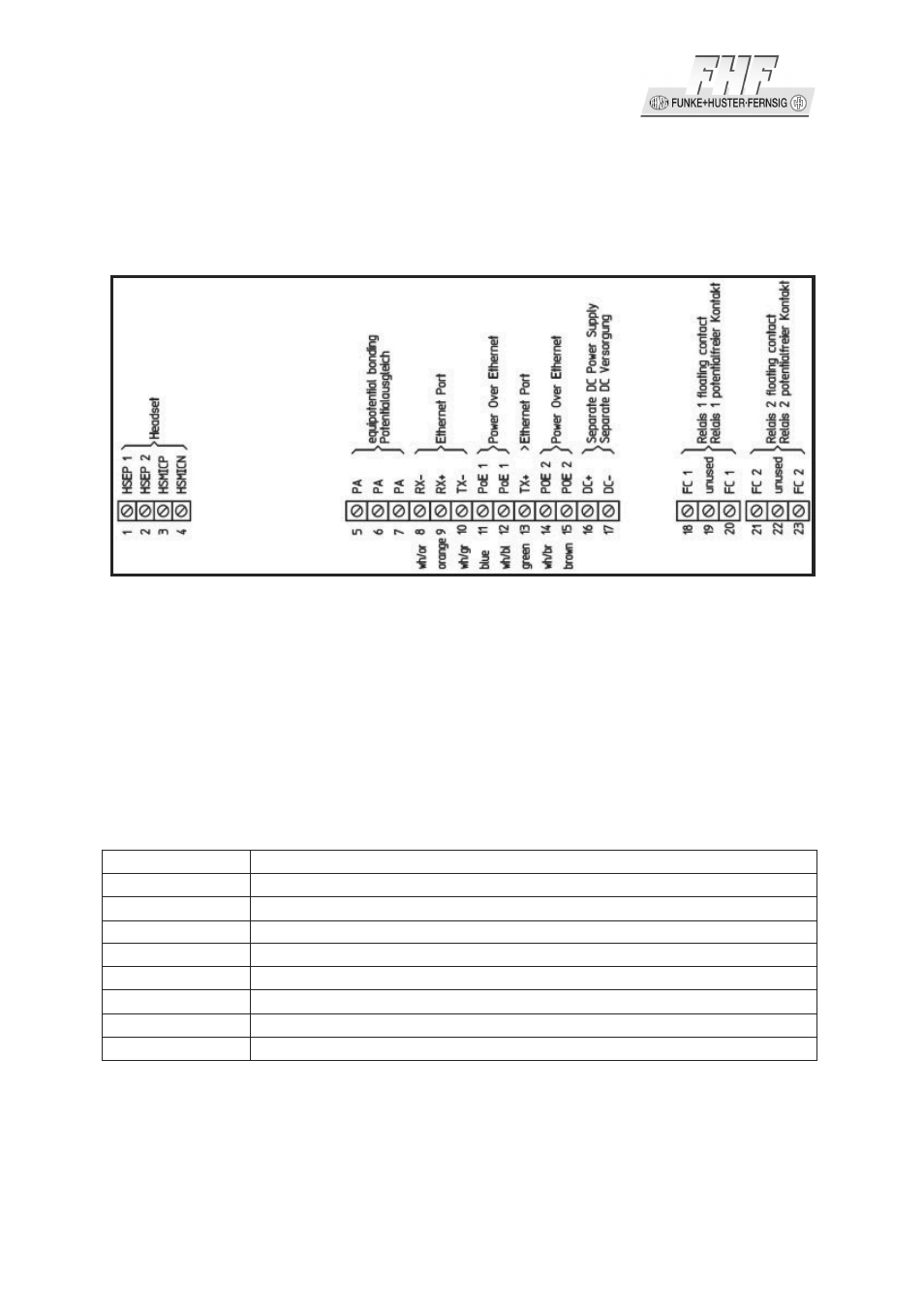
2.1.5 Connecting Plan
Figure 4: Terminals of the Explosion Proof VoIP Telephone ExResistTel IP2
2.1.6 Connection Potential Equalisation
The terminals 5 – 7 are available for the potential equalisation. The terminal 5 is
reserved fort he connection of the printed board with the potential equalisation bolt.
2.1.7 Ethernet Connection
At the terminals 8 – 15 the Ethernet cable inclusive PoE can be connected. The
assignment is as follows:
terminal
description
8
Rx –
9
Rx +
10
Tx –
11
PoE1
12
PoE1
13
Tx +
14
PoE2
15
PoE2
Table 1: Ethernet Connection of the ExResistTel IP2
PoE will be supported with the unused pairs of data lines of a 10/100 Mbit/s Ethernet
connection only. The polarity will be recognised by the phone automatically.