Ba c c, Ab c c – MCZ Vivo 70 Wood User Manual
Page 16
Chapter 4
INSTALLATION AND USE MANUAL
page
16
Installation and assembly
Technical service – MCZ Group S.p.A. all rights reserved - Reproduction prohibited
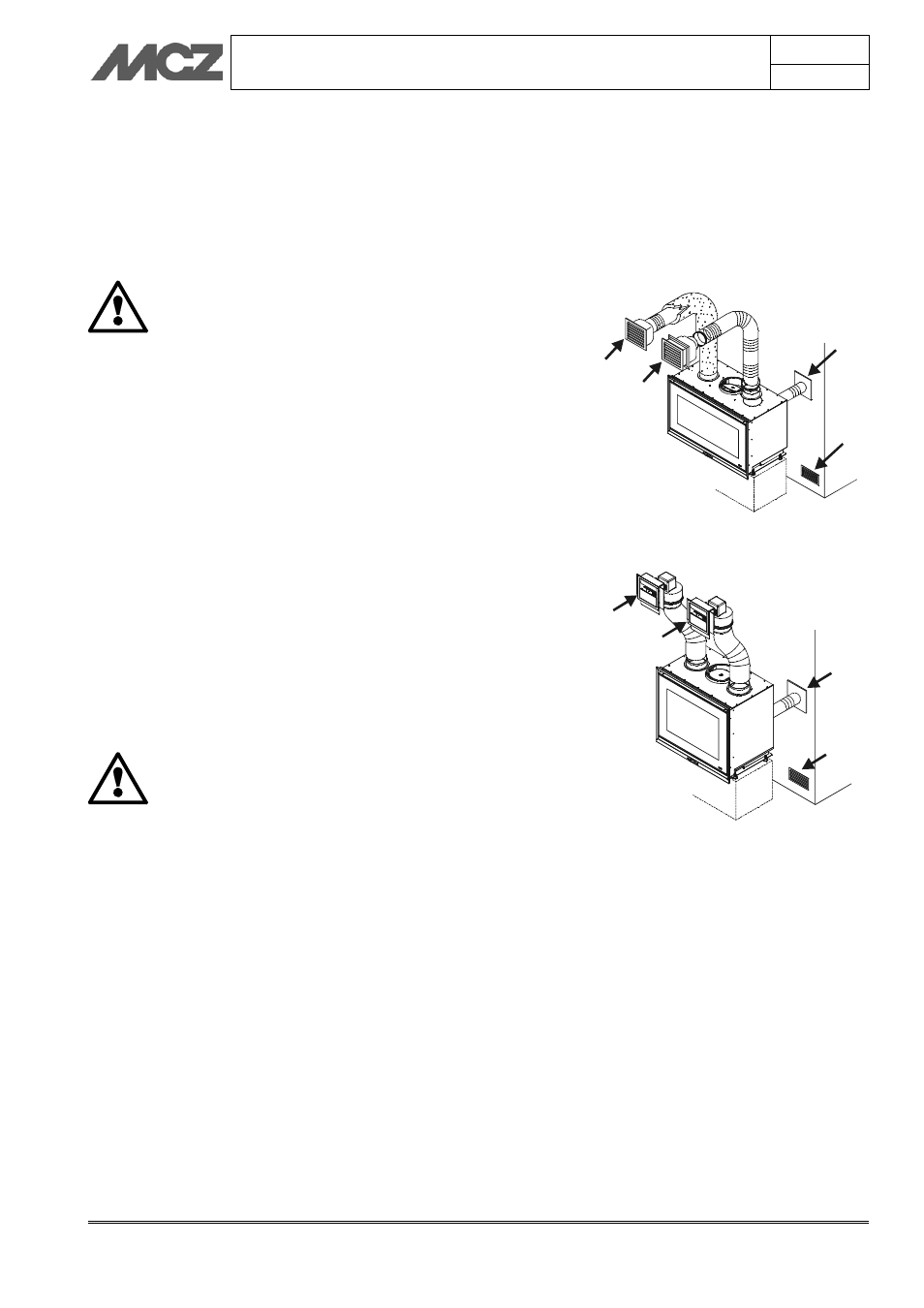
4.2.1. Natural convection (COMFORT AIR VN)
If this system is used, the installer must make a connection to the
outside (B) concerning the inlet of combustion air (fig.2), and an air
intake (A) for the inlet of fresh ventilation air inside the cladding.
For the ducting of hot air C, it is necessary the install the hoses Ø 150
mm C (optional) on the flanges located on the upper part of the stove
unit
ATTENTION!
FOR BEST OPERATION, MCZ STRONGLY SUGGESTS
CONNECTION THE COMBUSTION AIR INTAKE Ø100
DIRECTLY TO AN EXTERNAL AIR INTAKE.
4.2.2. Forced convection (COMFORT AIR VF)
Also in this case, it is necessary to connect the stove unit to an external
air intake (B) with a pipe Ø 100 (optional) using the flange located on
the back of the stove unit. (figure 1) If it is not possible to connect
directly to the air intake, at least connect the flange to the outside of
the cladding.
This operation is necessary to ensure proper operation of the
COMFORT AIR KIT. If the combustion air intake is not connected
directly to the an external air intake (B), it will be obligatory to provide
an air intake (A) that has a free passage of not less than 150 cm
2
so
that natural fresh air flows into the room of installation (preferably
inside the cladding).Figure 3
For the ducting of hot air, it is necessary to install a reduction flange Ø
100 on the upper connections of the stove unit. Then insert in the
flanges of the hoses Ø 100 the COMFORT AIR outlets (C).
Then proceed as set forth in
paragraph 5.3 “Installation of comfort air
kit".
ATTENTION!
FOR BEST OPERATION, MCZ STRONGLY SUGGESTS
CONNECTING THE COMBUSTION AIR INTAKE Ø100
DIRECTLY TO AN EXTERNAL AIR INTAKE OR AT
LEAST TO HAVE AIR DRAWN FROM OUTSIDE THE
CLADDING.
Figure 2 – Natural convection
A
B
C
C
B
A
C
C
Figure 3 – Forced convection