Configurations of terminals, Appendix, Control port connector – Eiki Multimedia Projector LC-XG400L User Manual
Page 75: Input 1/analog out, Terminal : mini din 8-pin, Terminal: analog rgb (mini d-sub 15 pin), Usb connector (series b) dvi-d terminal (digital)
75
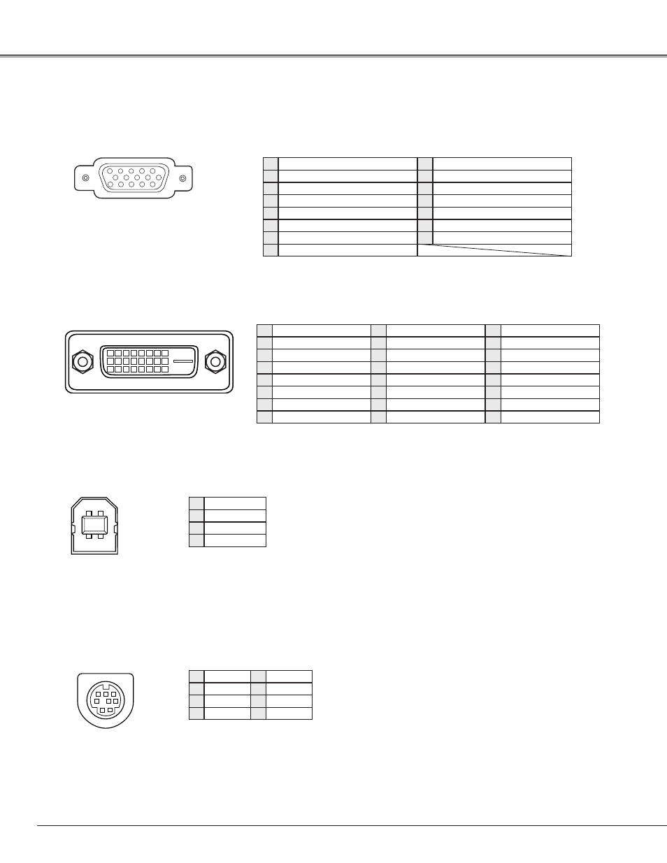
Terminal : Mini DIN 8-PIN
CONTROL PORT CONNECTOR
Vcc
- Data
+ Data
Ground
1
4
2
3
4
1
R X D
-----
-----
GND
RTS/CTS
GND
GND
1
4
5
6
7
8
INPUT 1/ANALOG OUT
Terminal: Analog RGB (Mini D-sub 15 pin)
5
1
2
3
4
10
9
6
7
8
15
14
13
11
12
Configurations of Terminals
Red (R/Cr) Input/Output
Ground (Horiz.sync.)
Green (G/Y) Input/Output
-----
Blue (B/Cb) Input/Output
Ground (Red)
Ground (Green)
Ground (Blue)
1
5
4
6
7
8
Horiz. sync. Input/Output (Composite H/V sync.)
Ground (Vert.sync.)
DDC Data/ -----
Ground/ -----
Vert. sync.
DDC Clock/ -----
9
1
10
1
11
14
15
T X D
USB CONNECTOR (Series B)
DVI-D TERMINAL (DIGITAL)
1
9
17
2
10
18
3
11
19
4
12
20
5
13
21
6
14
22
7
15
23
8
16
24
T.M.D.S. Data2–
No Connect
T.M.D.S. Data2+
No Connect
T.M.D.S. Data2 Shield
DDC Clock
DDC Data
Analog Vert. sync
1
5
4
6
7
8
T.M.D.S. Data1–
No Connect
T.M.D.S. Data1+
No Connect
T.M.D.S. Data1 Shield
+5V Power
Ground (for +5V)
Hot Plug Detect
9
1
10
1
11
14
15
16
T.M.D.S. Data0–
No Connect
T.M.D.S. Data0+
No Connect
T.M.D.S. Data0 Shield
T.M.D.S. Clock Shield
T.M.D.S. Clock+
T.M.D.S. Clock–
17
1
18
0
19
4
1
2
3
4
5
8 7 6
Appendix
+5V Power/ -----