Electro-voice, Standard placement & use guidelines, Locking switch feature – Electro-Voice PL24 User Manual
Page 2
12000 Portland Avenue South, Burnsville, MN 55337
Phone: 952/884-4051, Fax: 952/884-0043
www.electrovoice.com
© Bosch Communications Systems
09/2008
Part Number LIT000228 Rev C
U.S.A. and Canada only. For customer orders, contact Customer Service at:
800/392-3497 Fax: 800/955-6831
Europe, Africa, and Middle East only. For customer orders, contact Customer Service at:
+ 49 9421-706 0 Fax: + 49 9421-706 265
Other Internatonal locations. For customer orders, Contact Customer Service at:
+ 1 952 884-4051 Fax: + 1 952 887-9212
For warranty repair or service information, contact the Service Repair department at:
800/685-2606
For technical assistance, contact Technical Support at: 866/78AUDIO
Specifications subject to change without notice.
Electro-Voice
®
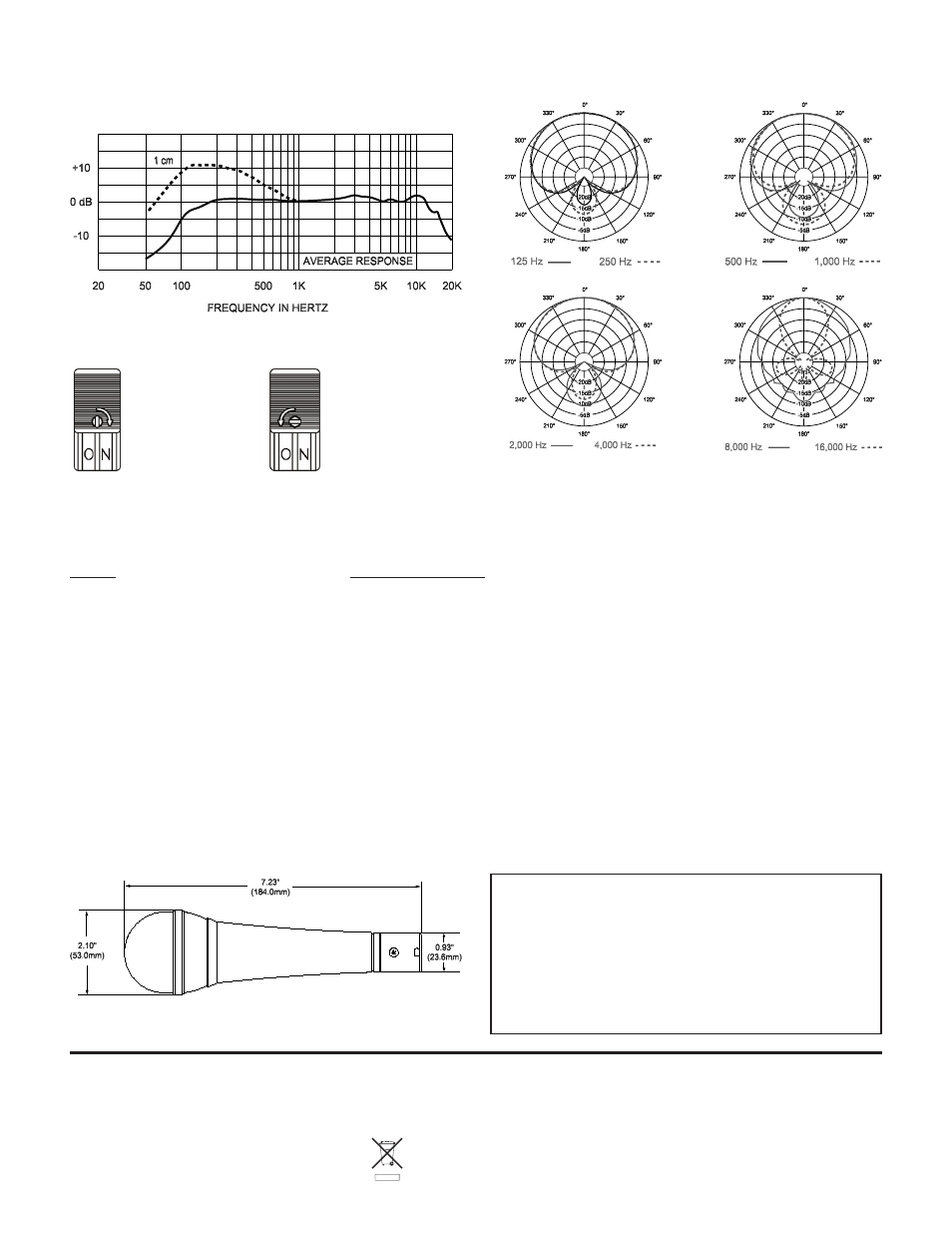
Dimension Drawing:
Frequency Response:
Polar Response:
Microphone Use and Placement
Please note that micing techniques are a matter of personal preference. These are merely guidelines to assist in the placement of the
microphone to gain optimal performance.
Usage
Optimal Placement
Vocals
0 to 6 inches away, aimed directly at the sound source.
Spoken Word
5 to 10 inches away, aimed directly at the sound source.
Standard Placement & Use Guidelines
1. Always point the microphone at the desired source of sound, and away from any unwanted sources.
2. The microphone should be located close to the sound source to minimize interference from other potential sound sources.
3. Use the 3-to-1 rule when using multiple microphones. Place each microphone three times farther from other microphones as from
the desired sound source.
4. Minimize over-handling of the microphone to reduce unwanted mechanical noise.
PL24 Part Numbers
PRD000157000 PL24, Dynamic Supercardioid Vocal
•
Microphone
PRD000157001 PL24S, Dynamic Supercardioid Vocal
•
Microphone with Switch
ACC000045000 SAPL-1, Replacement Microphone Stand
•
Adapter
ACC000048001 WSPL-1, Optional Foam Windscreen, Black
•
Locking Switch Feature
(switched versions only)
To lock the switch
in the “ON” position,
slide the switch up
and rotate the small
screw in the center
of the switch but-
ton clockwise 90° as
shown.
To unlock the switch,
turn the screw coun-
terclockwise 90°.