Warning – Emerson KF100AP01 User Manual
Page 6
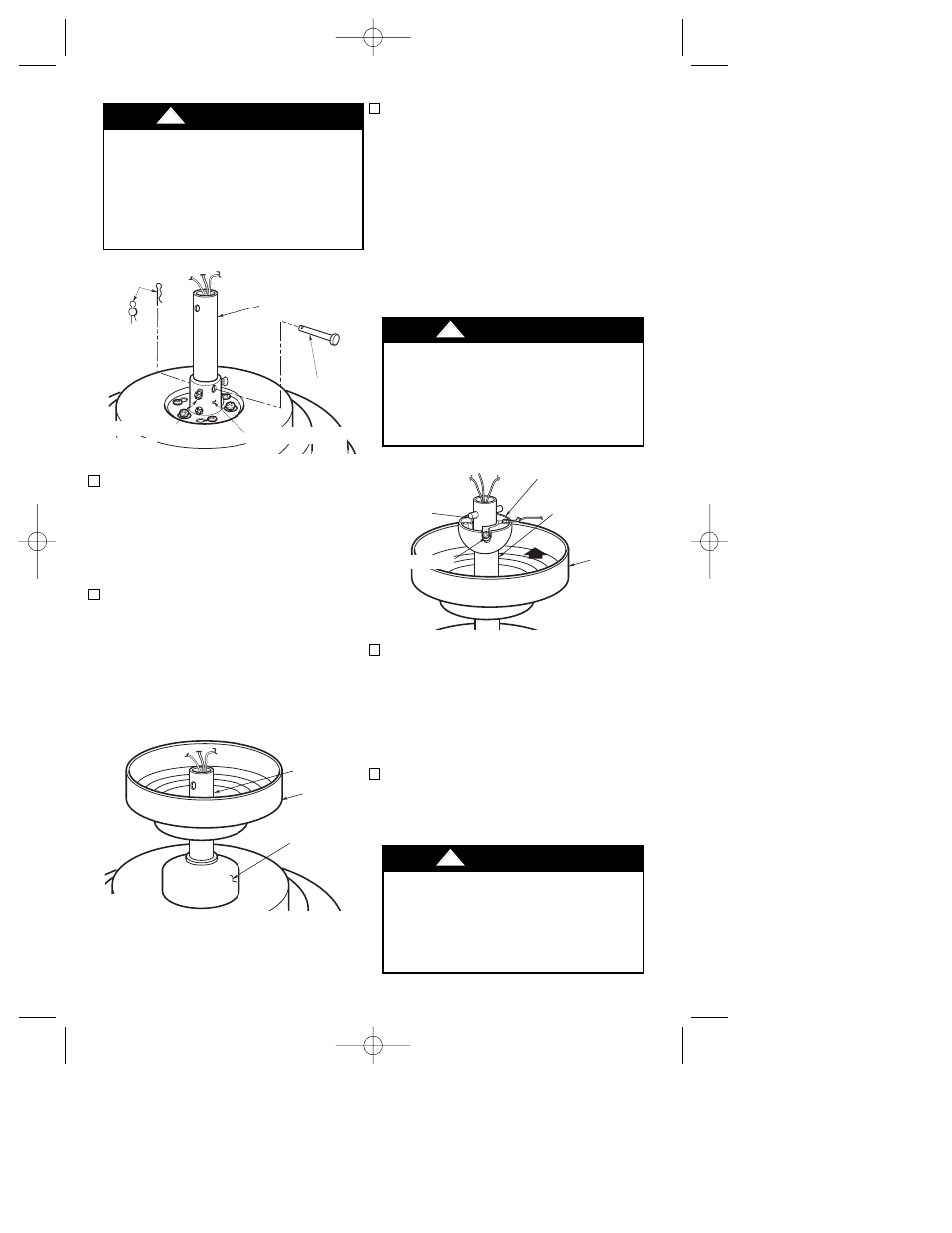
5. Reinstall the hanger ball (Figure 5) on
the downrod as follows. Route the
three 80” motor leads through the
hanger ball and slide the hanger ball
over the downrod. Position the pin
through the two holes in the downrod
and align the hanger ball so the pin is
captured in the groove in the top of the
hanger ball. Pull the hanger ball up tight
against the pin and securely tighten the
setscrew in the hanger ball. A loose
setscrew could create fan wobble.
6. The fan comes with blue, black and
white leads that are 80” long. Before
installing the fan, measure up approxi-
mately 6 to 9-inches above top of hang-
er ball/downrod assembly. Cut off
excess leads and strip back insulation
1/2” from end of leads.
7. Mount the fan blades to the blade
flanges using three 10-24 x 9mm truss
head screws and three fiber washers
(supplied) (Figure 6).
3. Tighten the setscrews (Figure 3)
securely while pulling up on the down-
rod.
NOTE: The setscrews must be properly
installed as described above, or fan
wobble could result.
4. Make sure the grommet is properly
installed in the coupling cover, then
slide the coupling cover on the down-
rod until it rests on the motor housing.
Place the ceiling cover over the down-
rod. Be sure that the ceiling cover and
the coupling cover are both oriented
correctly (Figure 4).
It is critical that the clevis pin in the
motor coupling is properly installed
and the setscrews securely tight-
ened. Failure to verify that the pin
and setscrews are properly installed
(as shown in Figure 3) could result in
the fan falling.
!
WARNING
It is critical that the pin in the hanger
ball is properly installed and the
setscrew securely tightened. Failure
to verify that the pin and setscrew
are properly installed could result in
the fan falling.
!
WARNING
To reduce the risk of personal injury,
do not bend the blade flange when
installing the blade flanges, balanc-
ing the blades or cleaning the fan. Do
not insert foreign objects in between
rotating fan blades.
!
WARNING
HAIRPIN
CLIP
DOWNROD
CLEVIS
PIN
SETSCREWS
MOTOR COUPLING
Figure 3
PIN
SETSCREW
HANGER BALL
DOWNROD
CEILING
COVER
Figure 5
CEILING
COVER
COUPLING
COVER
DOWNROD
Figure 4
6
BP7280, Olympia, KF100 7/31/06 10:57 AM Page 6