ETA Systems SM5505 User Manual
Page 20
Conditioned Power Center
20
Section 5 - Installation
Transformers are designed to meet a variety of requirements. Some locations (Europe, for example) have
standardized on a single input voltage. In other cases customers may specify multiple input voltages to
accommodate the variety of voltages commonly found in the United States. The CPC series conditioner can
accommodate either style of transformer - single voltage or multiple voltage primary.
The conditioner is a "delta-wye" system. The input or primary side of the transformer accepts power from either a
delta or wye power system at the voltages for which the transformer has been designed. Delta feeds are
desirable because they reduce wiring and installation costs by eliminating the neutral conductor from the input
wiring arrangement. In addition, feeding the CPC series with a higher input voltage reduces input amperage and
further reduces installation costs by allowing the use of less expensive, smaller gauge electrical conductors and
conduits. Consult the tag on the input circuit breaker. If the power conditioner you are installing has a single
voltage primary, the site voltage must match the transformer primary voltage. Power conditioners with multiple
voltage primaries may be changed to accommodate a variety of site voltages.
The secondary configuration of the transformer is a five wire wye requiring three phase conductors, a neutral,
and a safety ground.
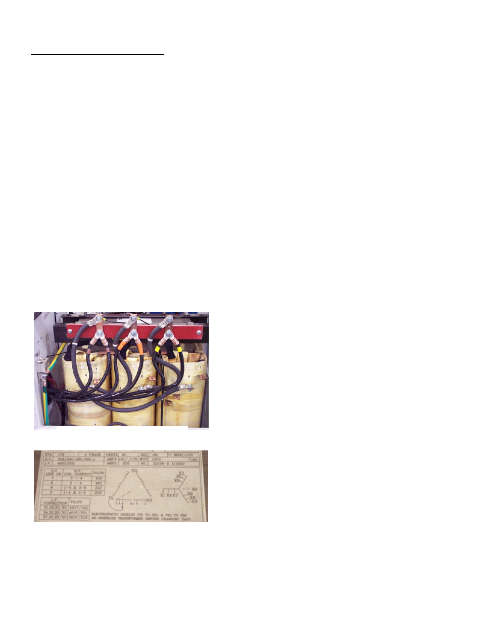
5.6.1 Transformer Primary Voltage Adjustment
Depending on the design of the isolation transformer, the
power conditioner may accommodate different input voltages.
The voltages are selected by changing primary taps. If
necessary, changes may be made to the input voltage setting
by changing connections on the transformer primary windings
at the locations shown in Figure F to the left. Most voltage
changes can be accomplished in 15 minutes or less. Consult
the specification sheet found in Section 10 of this manual for
detailed information on the specific connections required to
accommodate any of the allowable input voltages. In the event
that the voltage adjustment information in this manual is
missing, input voltage configuration information is also shown
on a data plate attached to the top of the transformer as shown
in Figure G to the left.
Figure F
Figure G