Extron Electronics VSC 100 User Manual
Page 10
Chapter 2 • Making Connections toand Operating the VSC 100
Extron • User’s Manual • VSC 100
Making Connections to and Operating the VSC 100 • Chapter 2
VSC 100 • User’s Manual • Extron
2-6
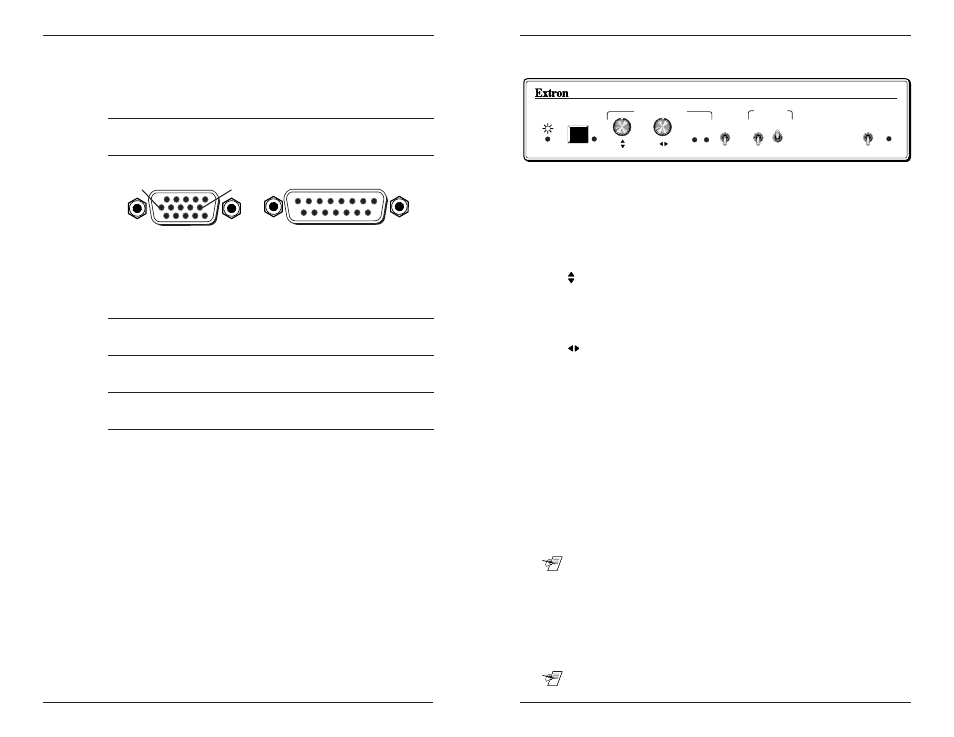
VSC 100 Front Panel Controls & Indicators
FREEZE
ZOOM
OVER
UNDER
CENTERING/PAN
VSC 100
FILTERING
HORZ
VERT
I
I I
I I I
S-VIDEO
RGB
I
I I
SCAN CONVERTER
MIN MAX
SIGNAL
LOCK
Figure 3-1. VSC 100 front panel
Power LED – Lights when power is applied to the unit.
Freeze – Provides a still image capture of a scan-converted computer
screen. Press to freeze; press again to unfreeze. The LED lights
when Freeze is active. Computer video (local monitor) output is
not affected.
Centering/Pan (Vertical) – This knob has 2 functions, depending on
the position of the Under/Over/Zoom switch. In Under/Over, it is
the vertical position (V. shift) adjustment – shifting the image up/
down on the screen. With the Under/Over/Zoom switch in Zoom, it
becomes the up/down pan control.
Centering/Pan (Horizontal) – This knob has 2 functions,
depending on the position of the Under/Over/Zoom switch. When
not in the Zoom position, it is the horizontal centering (H. shift)
adjustment – shifting the image left/right on the screen. When in
the Zoom position, it becomes the left/right pan control.
Min. Max. LEDs – One of these LEDs lights to indicate the Centering/
Pan range has reached its maximum or minimum limit.
Zoom/Over/Under – This switch provides three ways to view the
displayed image: Underscan, Overscan or Zoom.
• Zoom – The image becomes 200% of standard size. Use the
Under/Over/Zoom switch together with the Centering/Pan control
knobs to zoom and pan the image.
• Overscan – This gives a 10% larger image than standard size.
• Underscan – This is for normal viewing.
__ Nonvolatile memory saves centering adjustments for all views.
Filtering switch (Horz) – Selects from two levels of horizontal
filtering for different types of images. Select the position that gives
the best picture detail.
Filtering switch (Vert) – Selects from three levels of vertical filtering
to eliminate flicker when displaying different types of images, such
as text, graphics, etc. Select the position that gives the best picture.
__ It may be appropriate to change the vertical filtering setting after
switching between the Zoom/Over/Under modes.
Video Connector (Cable) Pin-outs
Following is a list of signals, together with their pin assignments on
both the VGA and the Mac connectors. The illustration shows the
pin numbers as they appear on the female connector.
VGA Pin
Function
Mac Pin
1
Red video
2
2
Green video
5
3
Blue video
9
4
ID bit
4
5
ID bit
8
6
Red ground
1
7
Green ground
6
8
Blue ground
13
9
not used
10
Comp. & Vert. gnd 11,14
11
ID bit
7
12
ID bit
10
13
Horz. sync
15
14
Vert. sync
12
15
ID bit/Comp sync
3
2-5
D15 Pin Locations
Male
1
8
9
15
HD15 Pin Locations
Male
1
5
11
15
10
6