Exmark FR23KC User Manual
Page 20
15
2.11 TORQUE REQUIREMENTS
Bolt Location
Torque
Cutter Housing Spindle Nut (secured with threadlocker) 160-185 ft-lbs. (217-251 N-m)
Blade
Mounting
Bolt............................................................... 55-60 ft-lbs. (75-81 N-m)
Sheave
Mounting Nut ...................................................... 90-110 ft-lbs. (122-149 N-m)
Engine Deck/Front Frame Mount Bolts .................................. 30-35 ft-lbs. (41-47 N-m)
Anti-Scalp Roller (See Figure 7)
Nyloc Nut ...................................................................... 30-35 ft-lbs. (41-47 N-m)
Hex Capscrew............................................................... 50-55 ft-lbs. (68-75 N-m)
Engine Mounting Bolts .......................................................... 30-35 ft-lbs. (41-47 N-m)
Wheel
Lug
Nuts ................................................................. 90-95 ft-lbs. (122-129 N-m)
Wheel Motor Mounting Bolts................................................ 72-77 ft-lbs. (98-104 N-m)
Wheel Hub Slotted Nut .................................................. minimum125 ft-lbs. (169 N-m)
Rollover Protection System (Roll Bar) Mounting Bolts ........... 30-35 ft-lbs. (41-47 N-m)
Clutch Retaining Bolt (secured with threadlocker).................. 55-60 ft-lbs. (75-81 N-m)
3. OPERATION INSTRUCTIONS
3.1 CONTROLS
3.1.1 Familiarize yourself with all controls before operating the mower.
3.1.2 Motion Control Levers: Located on each side of the console. The left lever
controls the flow of hydraulic oil from the left hydrostatic pump to the left drive
wheel motor. The right lever controls the flow of hydraulic oil from the right
hydrostatic pump to the right drive wheel motor.
IMPORTANT: To begin movement (forward or backward) the operator must
be in the seat, the brake lever must be disengaged (pushed down) before
the motion control levers can be moved in or the engine will kill.
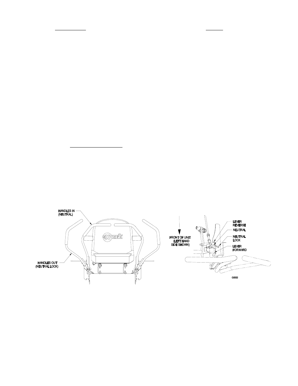
When levers are centered in the T-slot the drive system is in the neutral position.
With levers moved out in the T-slot the drive system is in the neutral lock position
See Figure 2.
FIGURE 2
By moving both levers an equal amount forward or back from the neutral position
the machine can be caused to move forward or backward in a straight line.
Movement of the left lever forward will cause the left drive wheel to rotate in a
forward direction. Movement of the right lever forward will cause the right
drive wheel to rotate in a forward direction. To stop forward travel, pull the
levers back to the neutral position.
To turn left while moving forward, move the left lever back toward neutral to
slow the left drive wheel.
To turn right while moving forward, move the right lever back toward neutral to
slow the right drive wheel.