Electrolux EKM 90410 X User Manual
Page 7
7
E 14
25 W - 230 V~
T300°C
A
GB
IMPORTANT
The wires in the mains
cable
are coloured
as follows
:
GREEN AND YELLOW........EARTH
BLUE....................................NEUTRAL
BROWN ...............................LIVE
REPLACING
OF THE CABLE
If
the cable
becomes
damaged
or worn
, replace it,
observing
the
following instructions:
- open the box of the supply board as
shown
in
the
diagram
below;
- unscrew screw “A”
that secures
the cable;
- replace the cable with one of the same
length
and
which corresponds
to
the features described
in
the table; switch the appliance off, and
shut
the gas tap;
-
connect
the ‘green-yellow” earth wire to the terminal “ “, leaving
it approximately
10 mm longer
than
the live
wire
;
-
connect
the “blue” neutral wire
to the terminal marked “N”
;
-
connect
the live wire
to the terminal marked “L”
.
Always isolate the cooker from the electricity supply,
shut
off the gas
supply temporarily and proceed as follows.
- change the injectors,
- adjust the minimum flow of the burners.
REPLACEMENT OF
COOKTOP
INJECTORS
To change
the
cooktop
injectors,
proceed
as follows: remove the
grids, remove burners and flame-spreaders (see fig.A), change the
injector (see fig.B) and replace it with another one suitable for the
new type of gas (see table D). Re-assemble everything in
reverse
order
,
ensuring you position
the flame-spreader
correctly
.
This appliance must be installed by a qualified person in
accordance with the
latest IEE
Regulations and in compliance
with the
manufacturer’s
instructions.
Check
that the voltage is the same as that stated on the rating plate.
The rating plate
is located
on the back cover.
WARNING! THIS APPLIANCE MUST BE EARTHED
If an fixed appliance is not equipped with supply cable and plug, the
power supply must be fitted with a disconnect switch in which the
distance between contacts permits total disconnection in accordance
with overvoltage category III, as required by installation regulations.
We recommend that the cooker circuit is rated to 13 amps.
Cable type HO5 RRF 3 X 1.5 mm
2
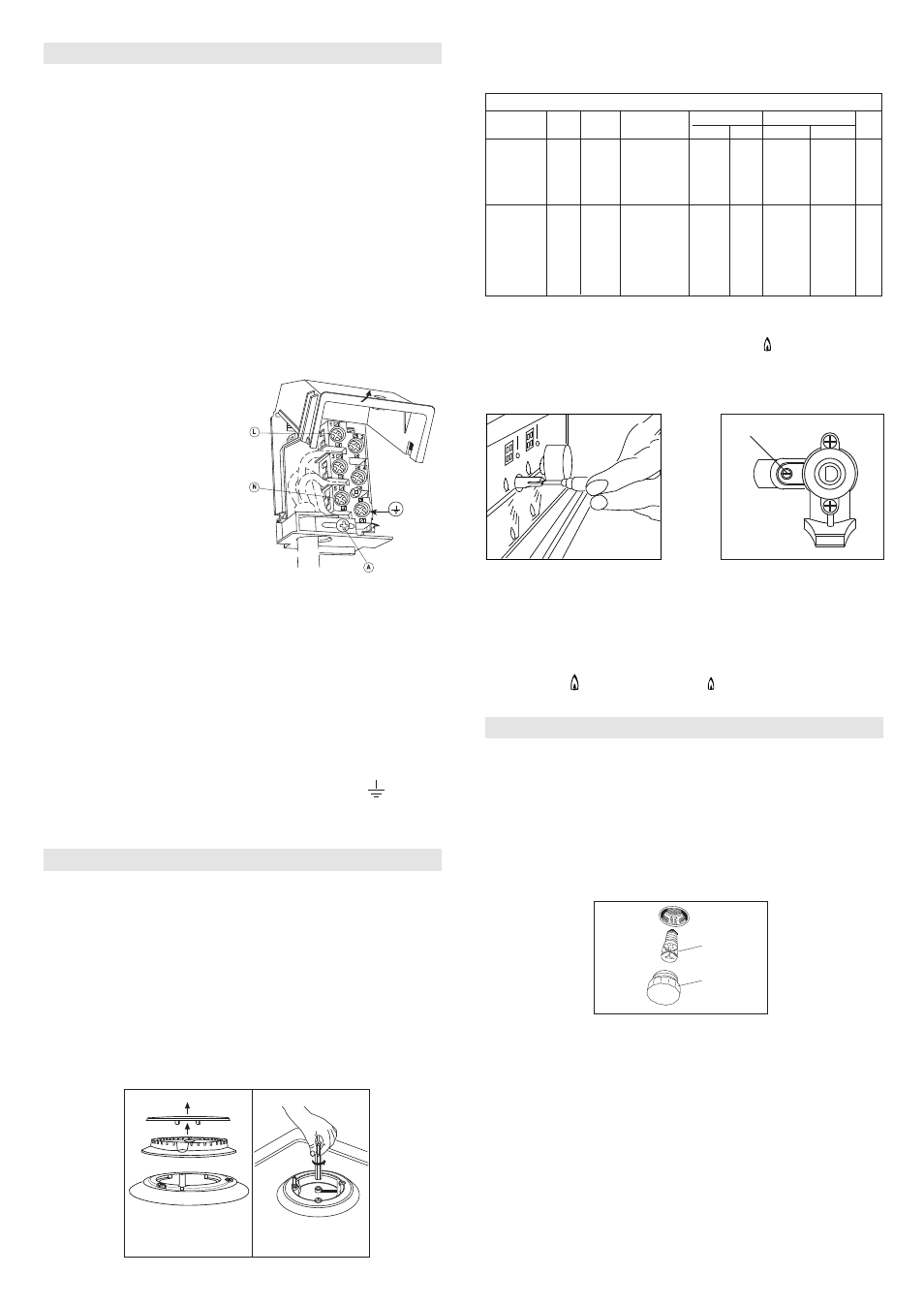
Connecting the mains cable
Open the mains terminal block cover as shown, unscrew screw “A”
the cable clamp
,
and
loosen
the screws in the mains terminal block
“L N E” which secure the three
wires of the mains cable. Fit the
cable and refit screw “A”
,
the cable
clamp.
Allow sufficient cable length for the
cooker to be pulled out for cleaning,
but do not let it hang
lower
than
50mm (2”)
from
the floor. The cable
can be looped if necessary, but
make sure that it is not kinked or
trapped when the cooker is in
position.
A
B
Fig. 11
MINIMUM FLOW ADJUSTMENT FOR
COOK
TOP TAPS
To adjust the minimum,
proceed
as follows: switch the burner on, and
turn the knob towards the minimum flow position
.
Remove the knob
from the tap, introduce a
small
screwdriver in
to
the tap rod (fig. 11).
Attention: in taps with security valve, the minimum
adjustment
screw
“Z” is placed outside the
tap
rod (fig. 12).
WARNINGS
Isolate the cooker from the electricity supply before attempting to
replace the oven lamp.
The oven lamp
is of a special type
designed to
withstand high
temperatures. To replace it,
proceed
as follows:
remove
the protect
ive
glass (A) and replace the burn
t-out
bulb
with one of the same type.
Re
-fit
the protecti
ve
glass.
DISMANTLING THE COOKTOP
If it
becomes
necessary to repair or replace
internal
components,
proceed
as follows: remove the glass lid from its position
by sliding
off upwards.
Remove the grids,
the
burners and flame-spreaders (see fig. 13),
unscrew the visible screws “V”
located
on the
cooktop
(see fig. 14).
Dismantle the cooktop
by unscrewing the 4 rear screws “A” (see fig.
15 ).
Loosen
the
adjustment
screw in order to increase the flow or
tighten
it to decrease the flow.
The proper adjustment is obtained when the flame is
approximately
3 or 4 mm
in length
.
For butane/propane gas, the
adjustment
screw must be
fully
screwed
down
.
Make sure that the flame does not go out
when
passing quickly from
the max. flow
to the minimum flow .
Assemble the knob again.
Fig. 12
Z
Values referred to Hs - 15°C - 1013,25mbar
TAB. D
Cat. II 2H3+
TABELLA GENERALE INIETTORI
Kind of gas
mbar
Nozzle
Burners
Power
KW Consum
N° max. min. max. min.
115
Rapide
3,00 0,75 286 l/h 72 l/h reg.
NATURAL 20 97
Semi rapide
1,75 0,48 167 l/h 46 l/h reg.
G 20 72
Auxiliary
1,00 0,33 95 l/h 31 l/h reg.
128
Triple crown
3,30 1,30 315 l/h 124 l/h reg.
BUTANE 28-30 85
Rapide
3,00 0,75 219 g/h 55 g/h 42
G 30 65
Semi rapide
1,75 0,48 128 g/h 35 g/h 31
50
Auxiliary
1,00 0,33 73 g/h 24 g/h 27
PROPANE 37 93
Triple crown
3,30 1,30 241 g/h 95 g/h 60
G 31
N°
By pass
ELECTRICAL CONNECTION
GAS ADJUSTMENT
APPLIANCE MAINTENANCE